Channel Estimation, Scheduling, and Resource Allocation using Pilot Channel Measurements

Inactive Publication Date: 2009-12-17
NOKIA CORP
View PDF14 Cites 47 Cited by
  • Summary
  • Abstract
  • Description
  • Claims
  • Application Information

AI Technical Summary

Benefits of technology

[0012]A further advantage of the present invention is that, with beam-specific pilot signals in at least the second set, the receivers do not need to know how the beams are formed at the transmitters. The number of beam patterns or the formation of

Problems solved by technology

Problems arise in these systems because making such resource allocations or optimizations in pseudo-randomly time-varying channels is extremely complicated and threatens to increase the complexity at the receiver level.

Method used


Image

  • Channel Estimation, Scheduling, and Resource Allocation using Pilot Channel Measurements
  • Channel Estimation, Scheduling, and Resource Allocation using Pilot Channel Measurements
  • Channel Estimation, Scheduling, and Resource Allocation using Pilot Channel Measurements

Examples


Example

[0023]The making and using of the presently preferred embodiments are discussed in detail below. It should be appreciated, however, that the present invention provides many applicable inventive concepts that can be embodied in a wide variety of specific contexts. The specific embodiments discussed are merely illustrative of specific ways to make and use the invention, and do not limit the scope of the invention.

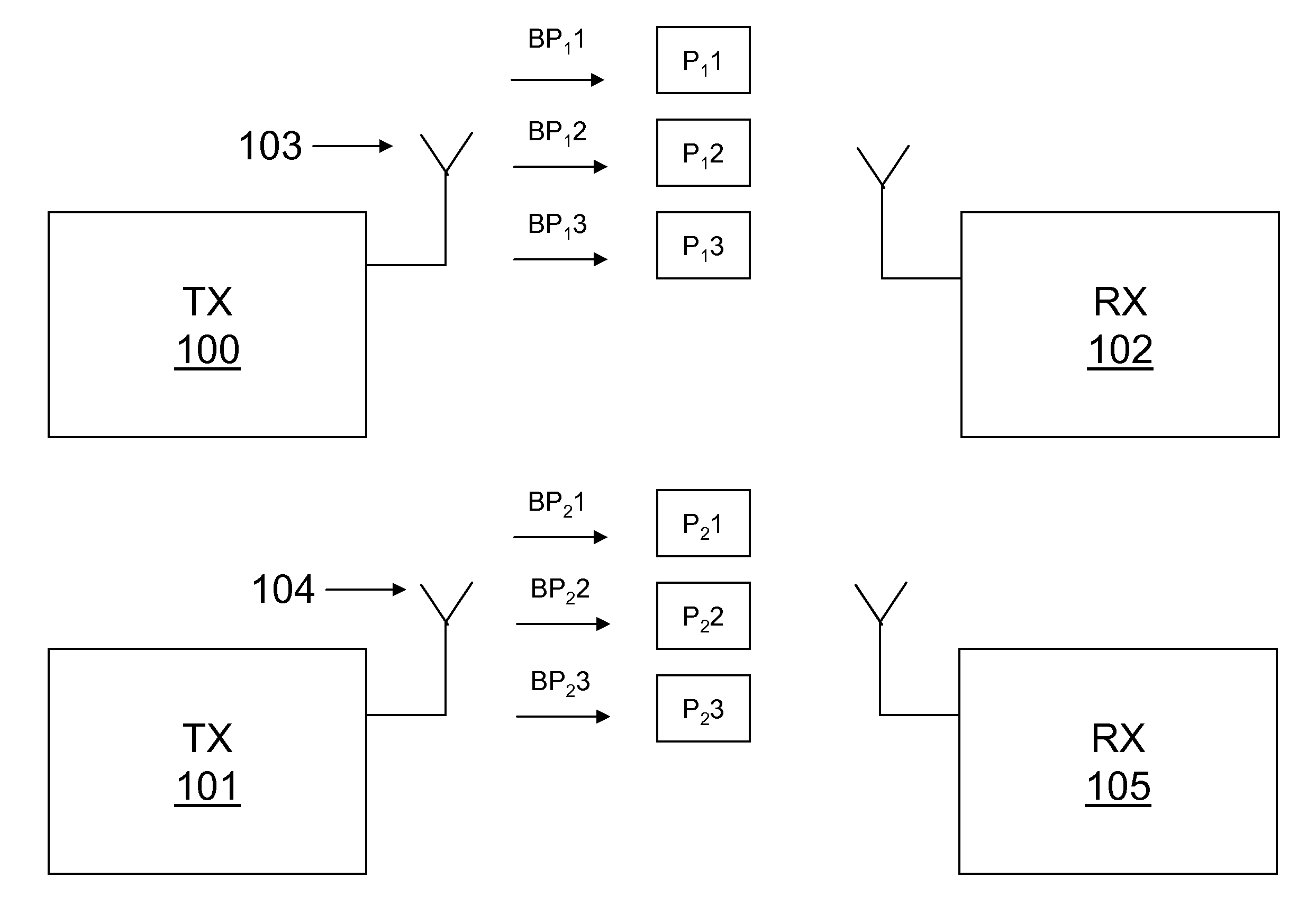
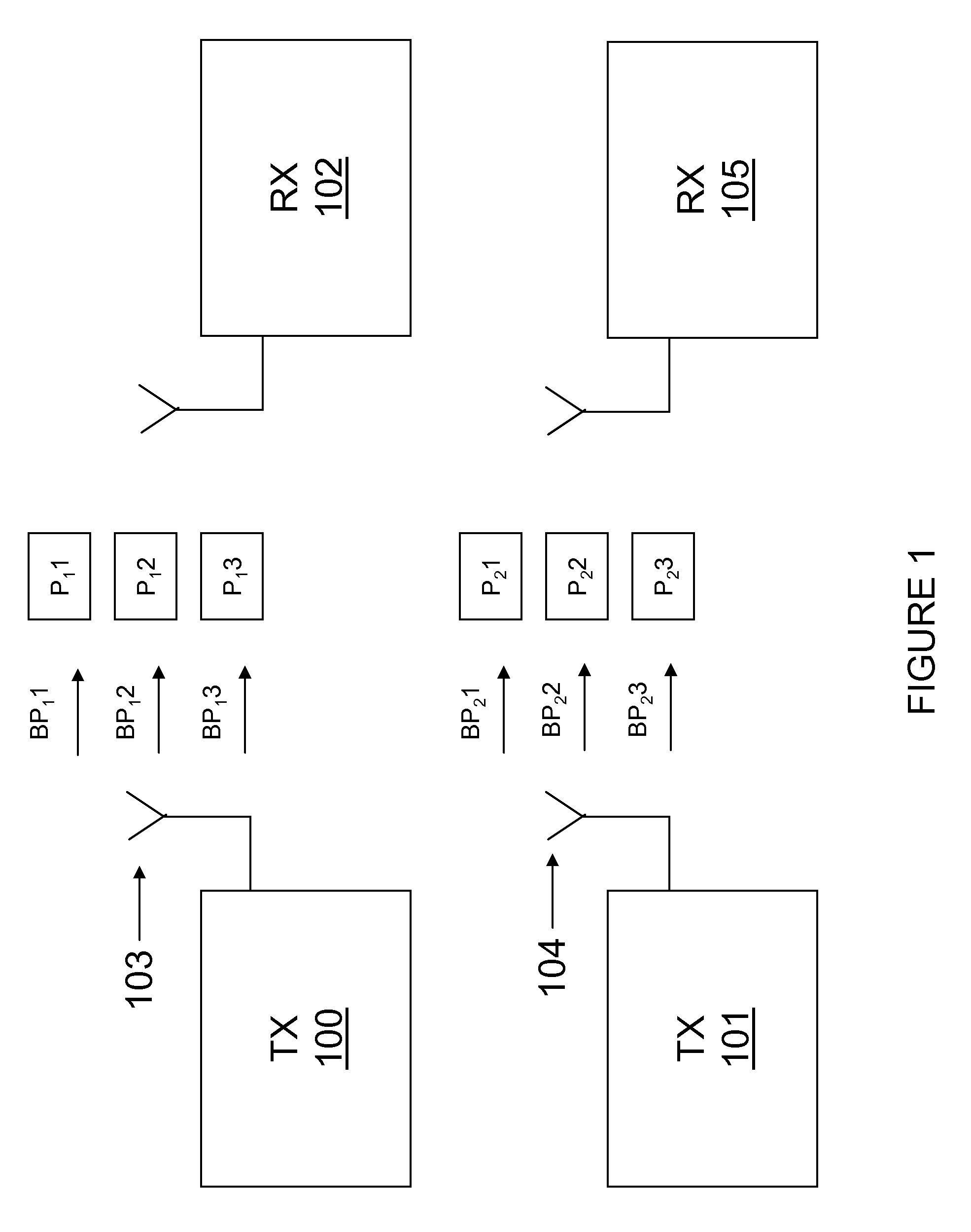
[0024]FIG. 1 is a block diagram illustrating wireless communications system configured according to one embodiment of the present invention. In example operation, wireless communications system includes transmitters (“Tx”) 100, 101, antennae 103, 104, and multiple receivers or ATs, such as receivers (“Rx”) 102, 105. At any given time or time interval, Tx 100 transmits a set of pilot signals, P11, P12, P13 using multiple beam patterns, BP11, BP12, BP13 over antenna 103. Similarly, Tx 101 transmits a set of pilot signals, P21, P22, P23, using multiple beam patterns, BP21, BP22,...


PUM


Abstract

A wireless communication system is disclosed that includes forming one or more beam patterns by a transmitter at a first time, where the beam patterns are made up of a first set of beam patterns used to transmit data during the first time, and a second set of beam patterns used to transmit data during a subsequent time. A pilot signal is transmitted on each of the beam patterns and is detectable and decodable by one or more receivers. The receivers test the quality of the beam patterns and transmit an indicator to the transmitter that relates to one of the beam patterns that has a high channel quality. The transmitter determines channel estimation, transmission scheduling, and/or resource allocation based, at least in part, on the indicator.

Description

TECHNICAL FIELD[0001]The present invention relates, in general, to wireless communications systems and, more particularly, to channel estimation, scheduling, and resource allocation using pilot channel measurements.BACKGROUND[0002]Many modern wireless communications systems allocate system resources based, at least in part, on pilot channel measurements. For example, scheduling decisions are often based on pilot channel measurements in current third generation (“3G”) networks such as high speed data packet access (“HSDPA”) networks, and networks based on the Institute of Electrical and Electronics Engineers (“IEEE”) 802.16e specification, which is incorporated herein by reference. In such systems, base stations or other network nodes (sometimes referred to herein generically as “transmitters”) transmit a pilot channel. User equipment or another node in the network (sometimes referred to herein generically as “receivers” or “access terminals (“AT”)”) scan the various signals in its g...

Claims


Application Information

Patent Timeline
IPC IPC(8): H04Q7/20
CPCH04W24/10H04W48/08H04W72/1231H04W72/08H04W72/046H04W72/54H04W72/542
Inventor HOTTINEN, ARI
Owner NOKIA CORP
Why Eureka
Try Eureka