Heart activity sensor structure

a sensor and heart activity technology, applied in the field of heart activity sensors, can solve the problems of harsh conditions for measuring heart activity while exercising

Active Publication Date: 2014-11-20
POLAR ELECTRO
View PDF9 Cites 28 Cited by
  • Summary
  • Abstract
  • Description
  • Claims
  • Application Information

AI Technical Summary

Problems solved by technology

However, the conditions for measuring t...

Method used


Image

  • Heart activity sensor structure
  • Heart activity sensor structure
  • Heart activity sensor structure

Examples


Embodiment Construction

[0017]The following embodiments are exemplary. Although the specification may refer to “an”, “one”, or “some” embodiment(s) in several locations of the text, this does not necessarily mean that each reference is made to the same embodiment(s), or that a particular feature only applies to a single embodiment. Single features of different embodiments may also be combined to provide other embodiments.

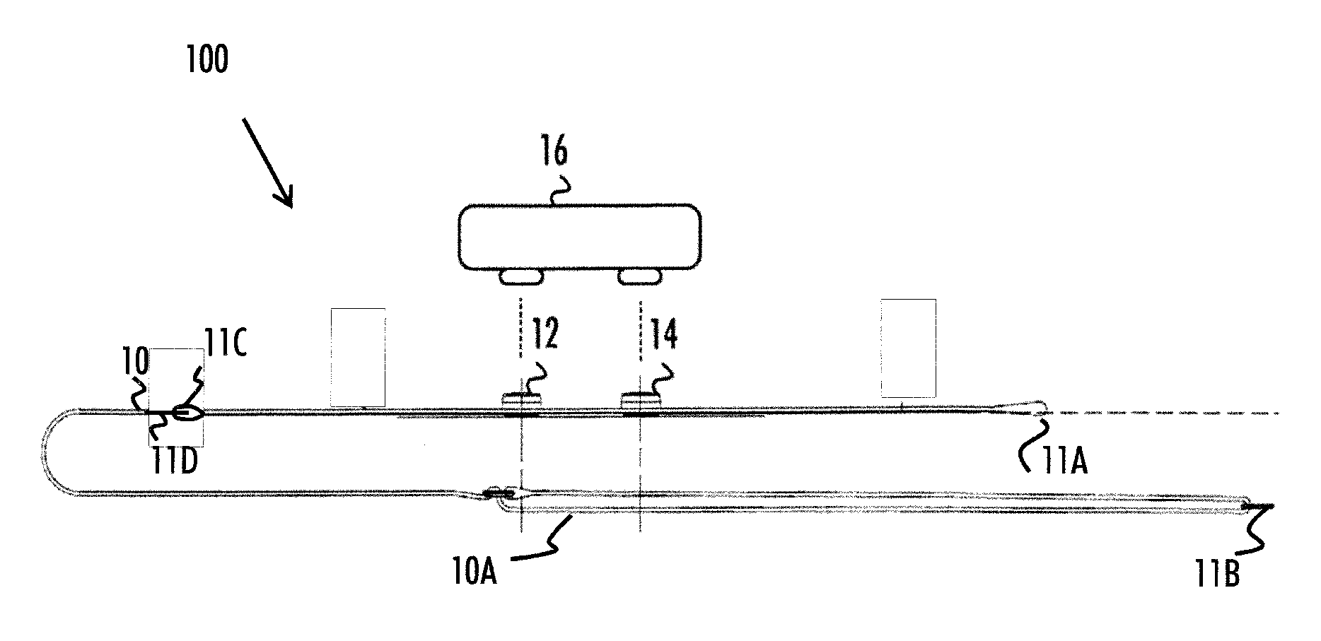
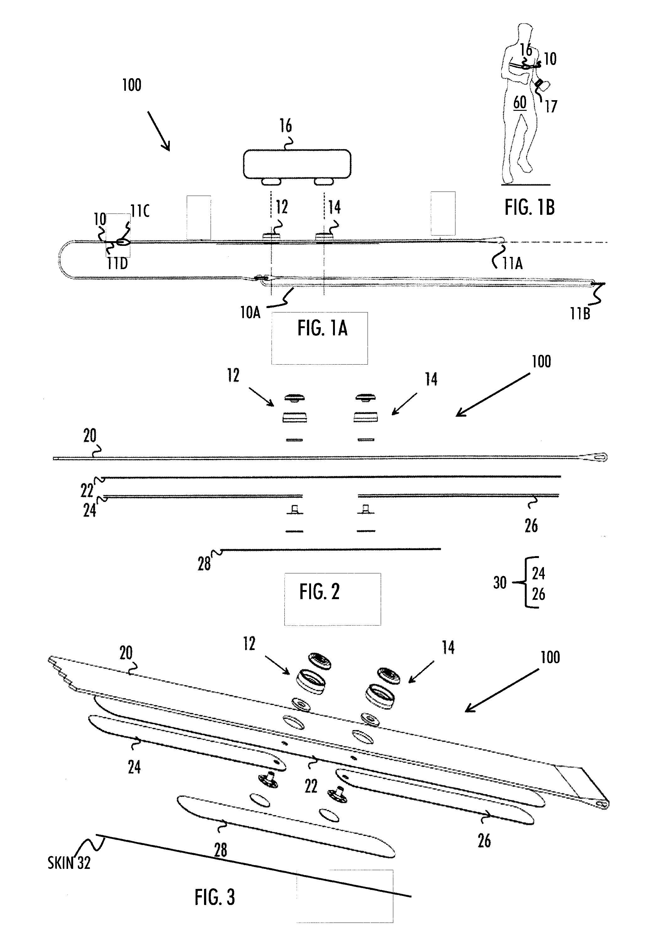
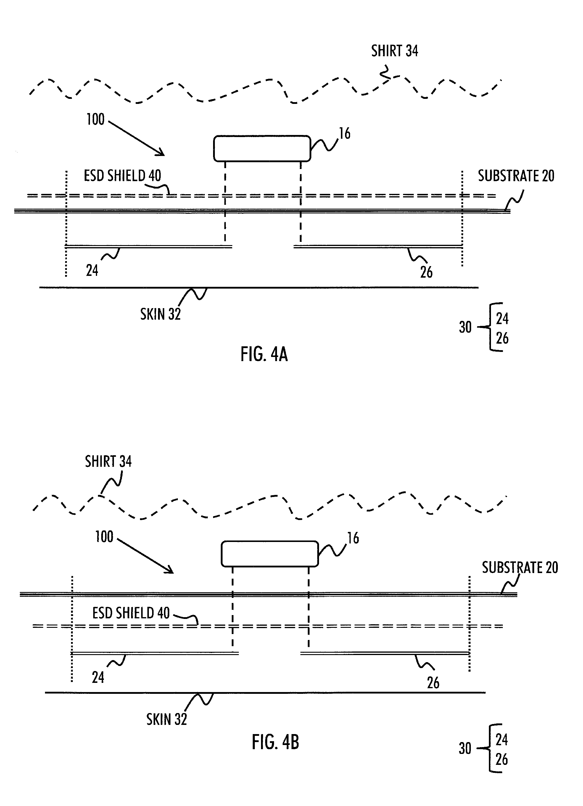
[0018]As said, it is common to measure heart activity while exercising in order to better monitor the effect of the exercise by the exerciser. Typically the measuring takes place with a heart rate activity sensor having electrodes against the skin of the exerciser. The location of the skin may be, e.g. the chest of the exerciser. The electrodes may measure voltage variations on the skin wherein the variations are due to the activity of the heart muscle. As a result, an electrocardiogram (ECG) signal may be generated. From the ECG signal, a variety of information may be derived. These inclu...


PUM

PropertyMeasurementUnit
Flexibilityaaaaaaaaaa
Electrical conductoraaaaaaaaaa
Areaaaaaaaaaaa

Abstract

A heart activity sensor structure includes a flexible textile substrate, and at least two electrodes with an electric insulation between each of the at least two electrodes. The at least two electrodes are applied on one side of the flexible textile substrate and configured to be placed against a skin of an exerciser in order to measure biosignals related to heart activity. The heart activity sensor also includes an electrostatic discharge shield applied on one side of the flexible textile substrate for protecting the at least two electrodes from static electricity.

Description

CROSS-REFERENCE TO RELATED APPLICATION[0001]This application claims priority to European Patent Application No. 13167788.2, filed May 15, 2013, which is incorporated by reference herein in its entirety.BACKGROUND[0002]1. Field The invention relates generally to heart activity sensors. More particularly, the invention relates to a structure of the heart activity sensor used while exercising.[0003]2. Description of the Related Art[0004]It is common to measure heart activity while exercising in order to better monitor the effect of the exercise by the exerciser. The measuring may comprise, for example, determining the heart rate or the heart rate variation of the exerciser. Typically this is done by wearing a heart rate activity sensor having electrodes against the skin of the exerciser. However, the conditions for measuring the heart activity while exercising are harsh.SUMMARY[0005]According to an aspect of the invention, there is provided a heart activity sensor structure as specifie...

Claims


Application Information

Patent Timeline
IPC IPC(8): A61B5/0408A61B5/00
CPCA61B5/0408A61B5/6804A61B5/6823A61B5/6831A61B5/0245A61B2562/164A61B2562/182Y10T29/4913A61B5/282
Inventor KORKALA, SEPPOPEKONEN, ELIASKEMPPAINEN, JUHANIRYTKY, PEKKA
Owner POLAR ELECTRO
Why Eureka
Try Eureka