Engagement structure for a cable head

Active Publication Date: 2014-11-27
LINTEX
View PDF9 Cites 0 Cited by
  • Summary
  • Abstract
  • Description
  • Claims
  • Application Information

AI Technical Summary

Benefits of technology

[0008]The main object of the present invention is to

Problems solved by technology

However, the smaller sizes the electronic products have, the easier the thievery occurs, especially in hypermarkets and exhibitions.
However, the lock is too complicated to use.
The

Method used


Image

  • Engagement structure for a cable head
  • Engagement structure for a cable head
  • Engagement structure for a cable head

Examples


Example

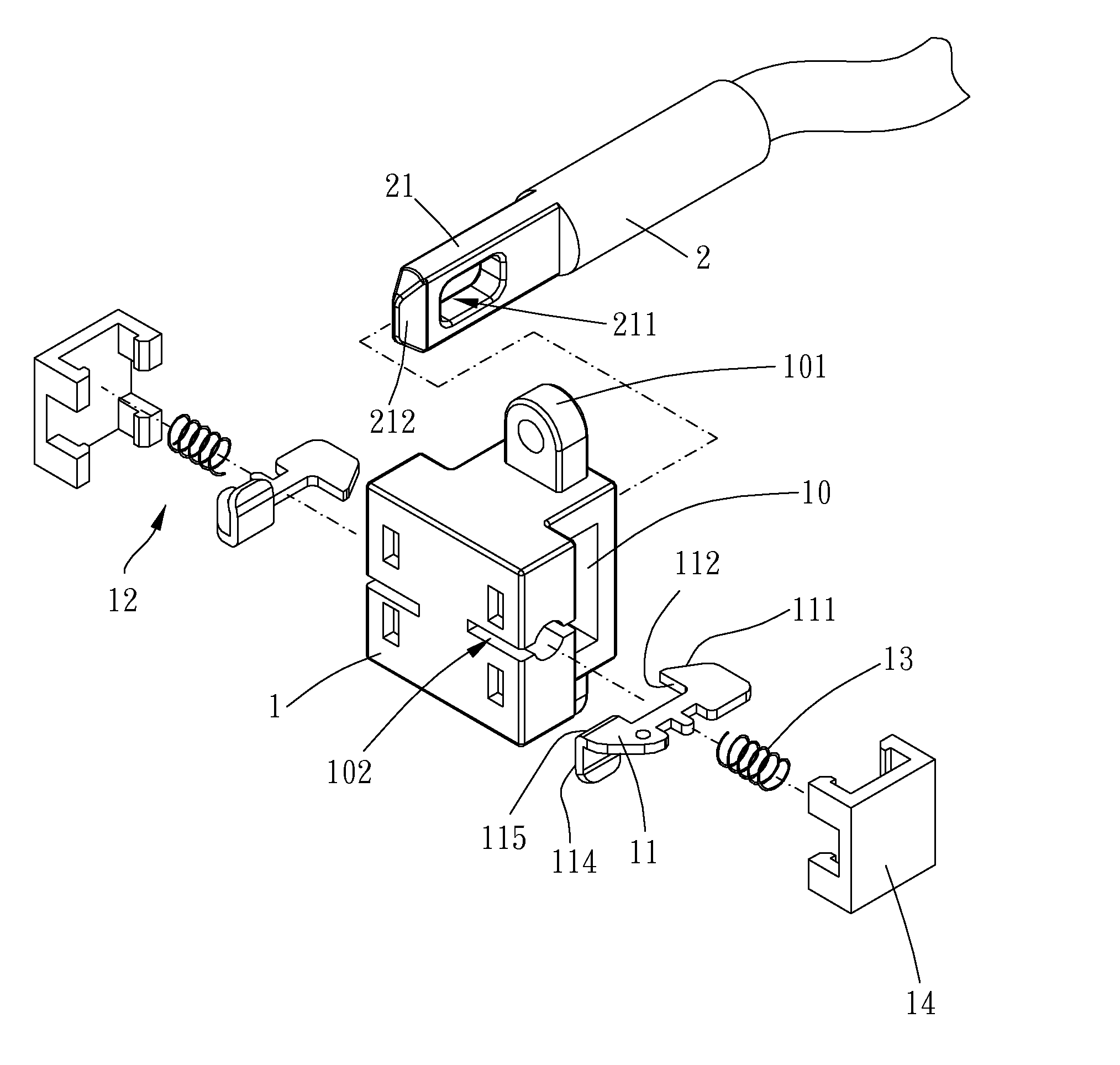
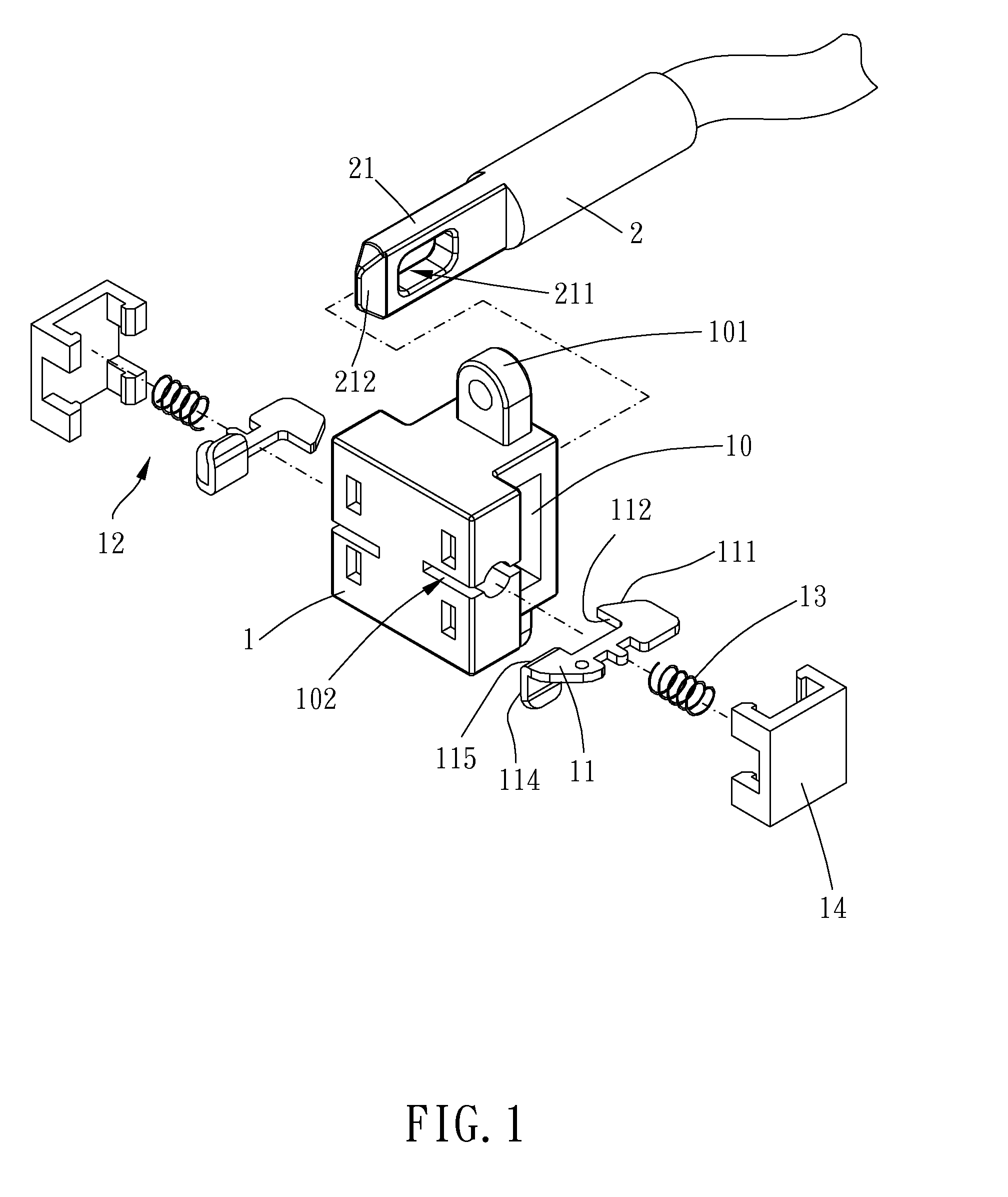
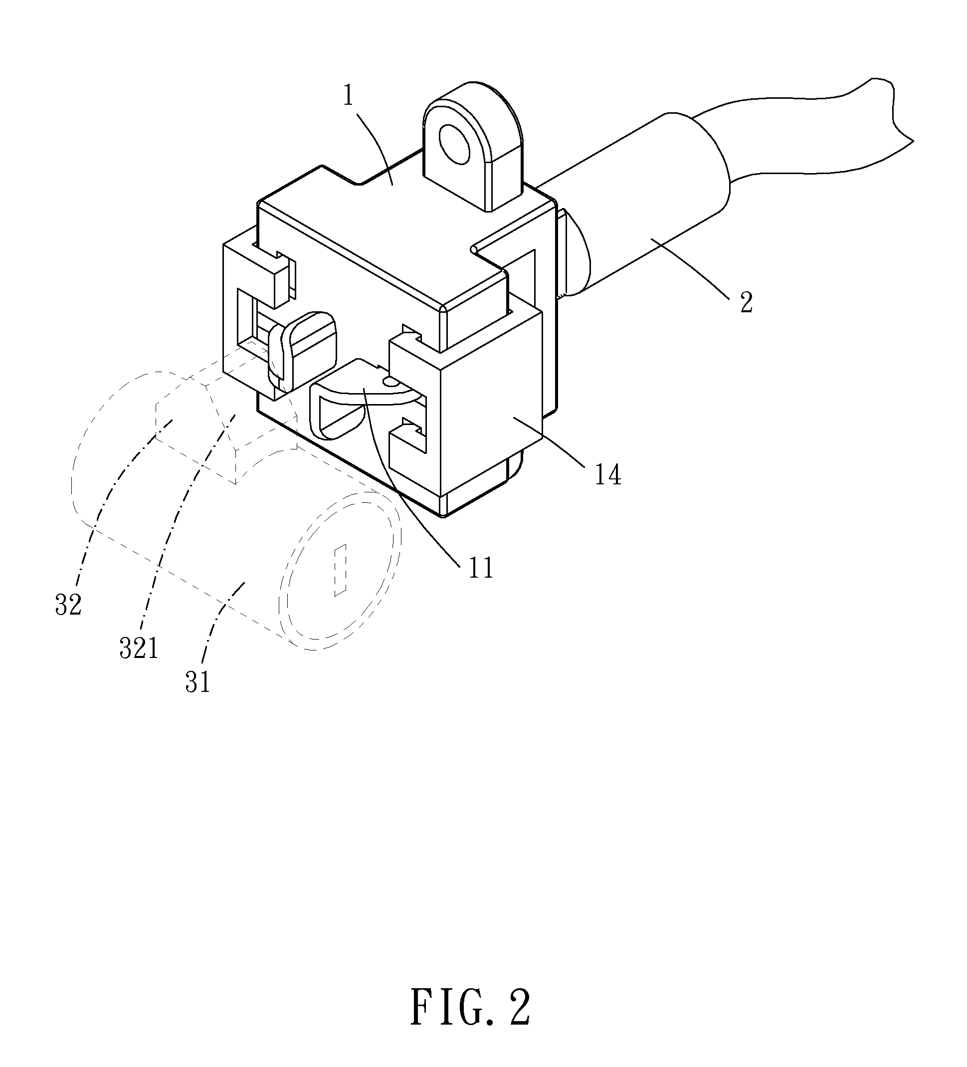
[0018]Please refer to FIG. 1 to FIG. 4 for a first embodiment of the present invention. The engagement structure for cable head of the present embodiment includes a main body 1, a cable head 2, and a release mechanism 3.

[0019]The main body 1 is formed with a through hole 10 and a connection portion 101. In the present embodiment, the connection portion 101 has a hole which is provided for fixing the main body 1 on an electronic product or other structures by threads. Of course, the connection portion may be provided in other formation to mate with the structure with which the engagement structure is going to fit. The main body 1 has two fixation members 14 oppositely fixedly disposed thereon, two grooves 102 oppositely arranged and laterally slit at two opposite sides thereof, two positioners 11 oppositely slidably arranged in the two grooves 102 and substantially in parallel, and an elastic mechanism 12 which are disposed between the two fixation members 14 and the two positioners ...

Example

[0027]Please refer to FIG. 5 to FIG. 9 for a second embodiment of the present invention. In the second embodiment, each of two fixation members 14′ projects on an outside surface of the main body 1 and near one the groove 102, each fixation member 14′ has an installation portion such as a post 141, and the two installation portion oppositely laterally face each other, that is, the two posts 141 are oppositely laterally extending. It is noted that the installation portion may be provided in other type of structure such as, but not limited to, a recess. Each installation post 141 corresponds to one the part of the positioner 11, and the two positioners 11 are urged between the two installation posts 141 by the two springs 13. The release mechanism 3 is selectively swingable toward the two positioners 14′ to move the two positioners 14′ substantially in parallel away from each other, so that the block of the two positioners 14′ and the insertion end 21 is released.

[0028]It is noted tha...


PUM


Abstract

An engagement structure for a cable head includes a main body and a release mechanism. The main body has movable positioners disposed thereon. When the cable head is inserted in the main body, the positioners are temporarily pushed away and moved back by an elastic mechanism to block the cable head from removing from the main body. For removing the cable head, a release mechanism is configured for pushing the positioners away. Thus, user can remove the cable head by operating the release mechanism. Therefore, operation of the engagement structure is simplified for user.

Description

BACKGROUND OF THE INVENTION[0001]1. Field of the Invention[0002]The present invention is a CIP of application Ser. No. 13 / 739,971, filed Jan. 11, 2013, the entire contents of which are hereby incorporated by reference.[0003]2. Description of the Prior Art[0004]Accompanied with technology improvement, electronic products, such as mobile phones and tablet personal computers, are now popularized to consumer. To fulfill portability purpose, the electronic products are provided with minimized sizes. However, the smaller sizes the electronic products have, the easier the thievery occurs, especially in hypermarkets and exhibitions. To preventing thievery, the electronic products are always firmly engaged with and protected by locks. Thus, unauthorized possession of the electronic products can be effectively forbidden.[0005]In cases of computer, laptop computers are usually provided with slots with which are adapted for locks to engage. Conventional locks, such as the lock described in TW U...

Claims


Application Information

Patent Timeline
IPC IPC(8): E05B73/00
CPCE05B73/0005E05B73/0082Y10T70/402
Inventor LIN, CHIA-SHENG
Owner LINTEX
Why Eureka
Try Eureka