Atmospheric circulation system and method
a circulation system and atmospheric gas technology, applied in the field of fluid mechanics, can solve the problems of not entirely clear what, whether the system would perform any of the tasks effectively, and the facility is extremely large and expensiv
- Summary
- Abstract
- Description
- Claims
- Application Information
AI Technical Summary
Benefits of technology
Problems solved by technology
Method used
Image
Examples
first embodiment
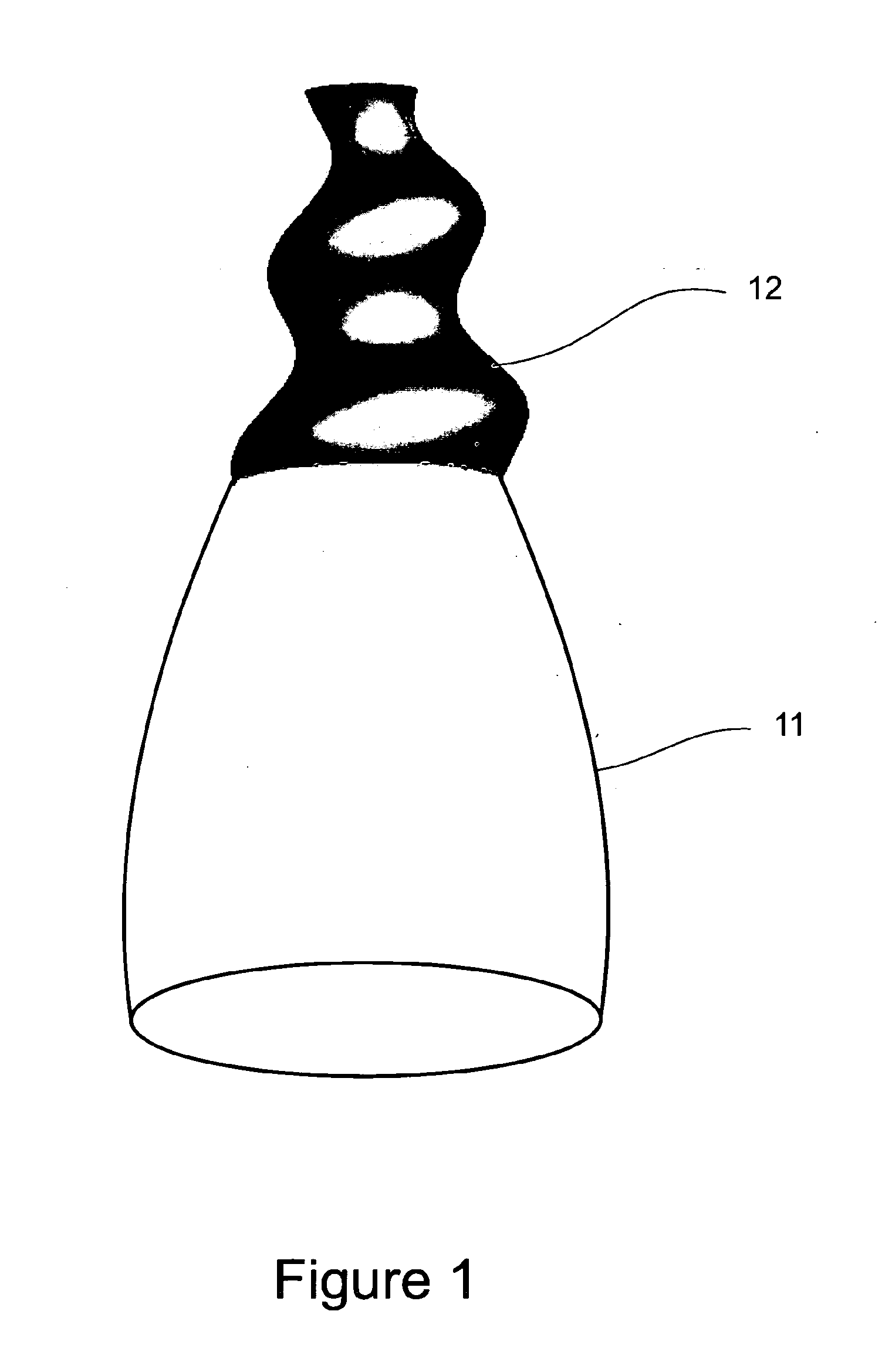
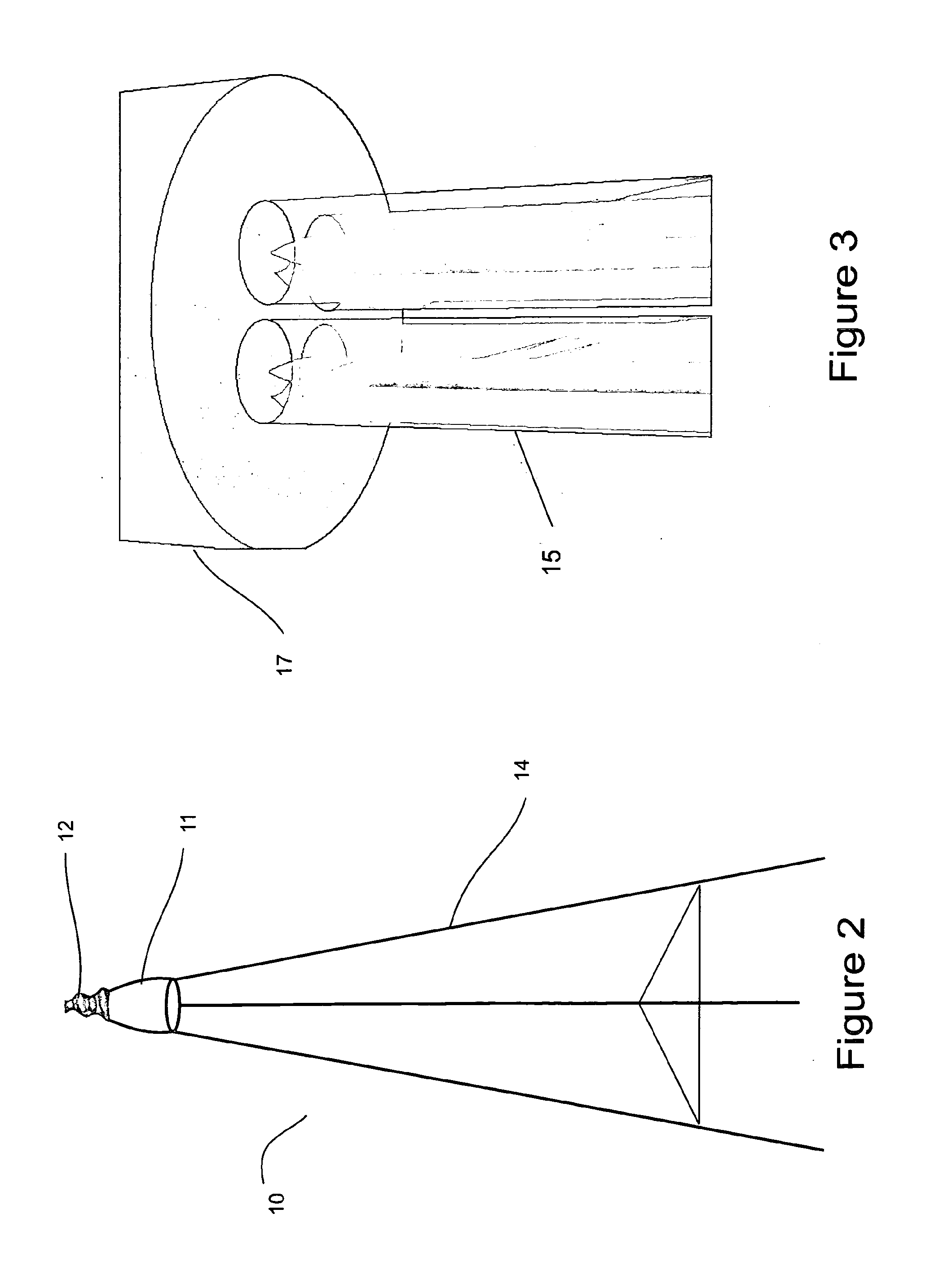
[0035]The atmospheric circulation system 1 according to the invention comprises one or more elemental vortex generating units 10. An elemental vortex generating unit 10 is illustrated in FIGS. 1 to 4. As shown in the drawings, the vortex generating unit 10 comprises a jet generating means 11, a vortex-inducing nozzle 12 and a support stand 14. The jet generating means 11 may comprise any suitable means to create a high speed jet of gas, and, in initial testing, jet engines used for commercial passenger aircraft have been found to be the most cost-effective means during the initial development and trials, as second hand engines may be obtained relatively cheaply. Nevertheless, it is to be appreciated that other jet emitting devices can be suitable, including but not limited to rocket engines. Initial testing suggests that each of these has advantages for certain applications.
[0036]Throughout the remainder of this specification, the jet emitting device is referred to as a jet engine,...
second embodiment
[0044]FIGS. 5 and 6 illustrate a group of vortex generating units. In this embodiment, swirl inducing devices are placed in the flow streams 21 exiting from the jet engines to induce rotation in the flow. The flow is the combined locally to create a single vortex 23, as is shown in FIG. 6.
[0045]A third embodiment of a vortex generating unit according to the invention comprises a fan or propeller driven by an appropriate motor. While a specific engine may be designed for the application, in initial testing and development an engine for a turboprop aeroplane has been found to be suitable. Preferably the fan is designed to provide both axial flow and rotation of the air flow relative to axis so that in this embodiment, no nozzle is required to cause the vortex flow. The patents of Jayden David Harman, U.S. Pat. No. 5,934,877 and U.S. Pat. No. 7,488,151 give guidance as to the principles required to optimize the design of the rotor to produce such an air flow. The disclosure of these pa...
third embodiment
[0047]However, the practical difficulty would lie in powering such a fan. The largest turboprop engines have a power less than one tenth of this amount. It may be possible to use power sources other than a jet engine, but alternatives have their own difficulties. For instance, a 50 MW electric motor is conceivable, but powering a cluster of ten or more units is not. It is understood that high power turboprop jet engines are at least being studied and implementation of the third embodiment may need to await their development.
[0048]The first and second embodiments have been directed to a jet engine incorporating a suitable nozzle on the outlet while the third describes an engine driving a propeller. A fourth embodiment of the jet generating means according to the invention is described with reference to FIGS. 7 and 8. In this embodiment, the jet generating means comprises a duct 41 through which gas is passed and ejected at an outlet 42. A nozzle insert 43 is located within the duct 4...
PUM
 Abstract
Description
Claims
Application Information
 - R&D
- Intellectual Property
- Life Sciences
- Materials
- Tech Scout
- Unparalleled Data Quality
- Higher Quality Content
- 60% Fewer Hallucinations
Browse by: Latest US Patents, China's latest patents, Technical Efficacy Thesaurus, Application Domain, Technology Topic, Popular Technical Reports.
© 2025 PatSnap. All rights reserved.Legal|Privacy policy|Modern Slavery Act Transparency Statement|Sitemap|About US| Contact US: help@patsnap.com


