Laser controlled internal welding machine for a pipeline

a technology of internal welding and welding machine, which is applied in the direction of soldering apparatus, manufacturing tools, auxillary welding devices, etc., can solve the problems of inability the accuracy of the position of the torch is difficult to assess, and the pipeline system for welding pipe segments typically lacks the capability to visually inspect the weld. to achieve the effect of effective and efficient filling

Active Publication Date: 2014-11-27
CRC EVANS PIPELINE INT INC
View PDF6 Cites 88 Cited by
  • Summary
  • Abstract
  • Description
  • Claims
  • Application Information

AI Technical Summary

Benefits of technology

[0010]The welding mechanism is preferably an internal welding machine that applies a weld (e.g., a gas metal arc weld “GMAW”) from inside the pipe segments to a face or edge joint of the segment and into a v-shaped opening formed by chamfered edges of the two pipe segments (other cross-sectional shapes other than a V may be used also). The welding mechanism includes a carriage capable of engaging the inner walls of the pipe to secure or lock itself within the pipe in a fixed position and a welding portion rotatably supported from the carriage within the pipe. Specifically, the internal welder is located within the aligned pipe and then positioned longitudinally so that a weld head or torch is in longitudinal proximity to the edge joint. The welding mechanism also includes a rotary mechanism for rotating the welding portion relative to the carriage. The weld head or torch is rotatably supported on the welding portion about the pipe longitudinal axis so that the torch may closely follow the entire interior joint interface in an orbital rotation. Specifically, during welding, the torch of the articulating head follows the edge joint around the entire interior circumference of the pipe applying weld material. In addition to circular rotation relative to the carriage, various control elements may move the weld head axially along the pipe relative to the carriage, radially toward and away from the joint, and pivotally about a point or axis (e.g., an axis parallel or perpendicular to pipe longitudinal axis A-A). A controller may direct the torches pivoting. These degrees of freedom of articulation allow the weld head to be very effective and efficient in filling in interface profiles optimally and where necessary.

Problems solved by technology

In this process it is sometimes difficult to assess the accuracy of positioning of the internal welder in general and the torch in particular.
It is even more difficult to assess the accuracy of the position of the torch as the torch traverses the inside of the pipe along its orbital path during welding.
Moreover, conventional pipeline systems for welding pipe segments will typically lack a capability to visually inspect the weld applied by the torch.

Method used


Image

  • Laser controlled internal welding machine for a pipeline
  • Laser controlled internal welding machine for a pipeline
  • Laser controlled internal welding machine for a pipeline

Examples


Embodiment Construction

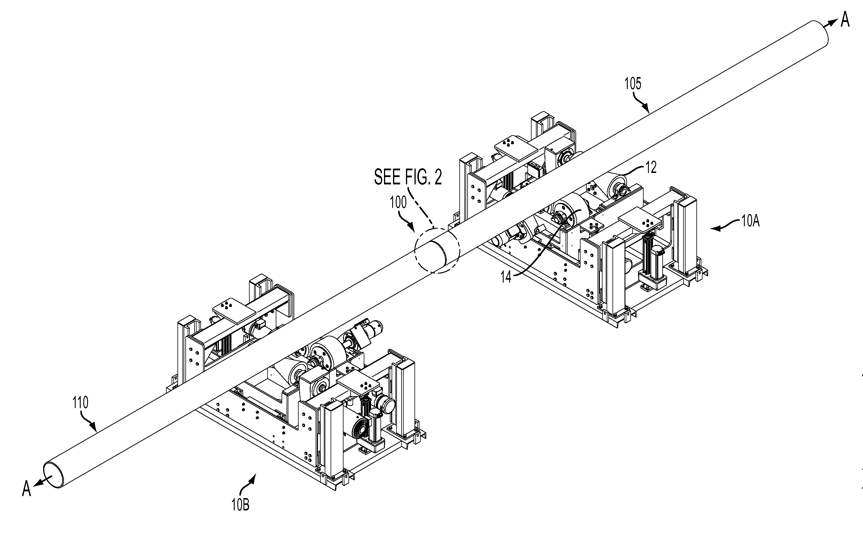
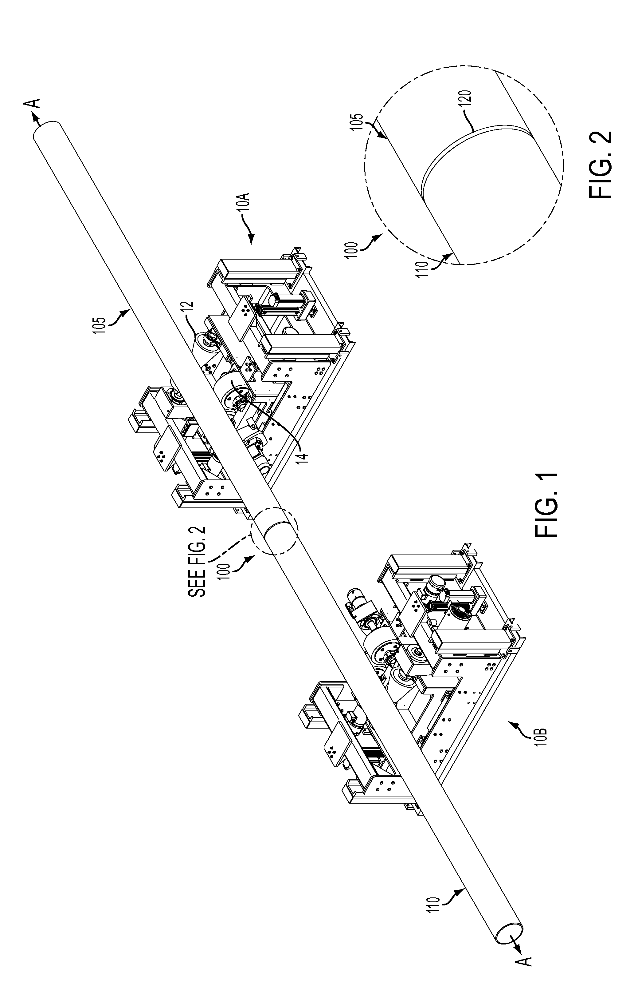
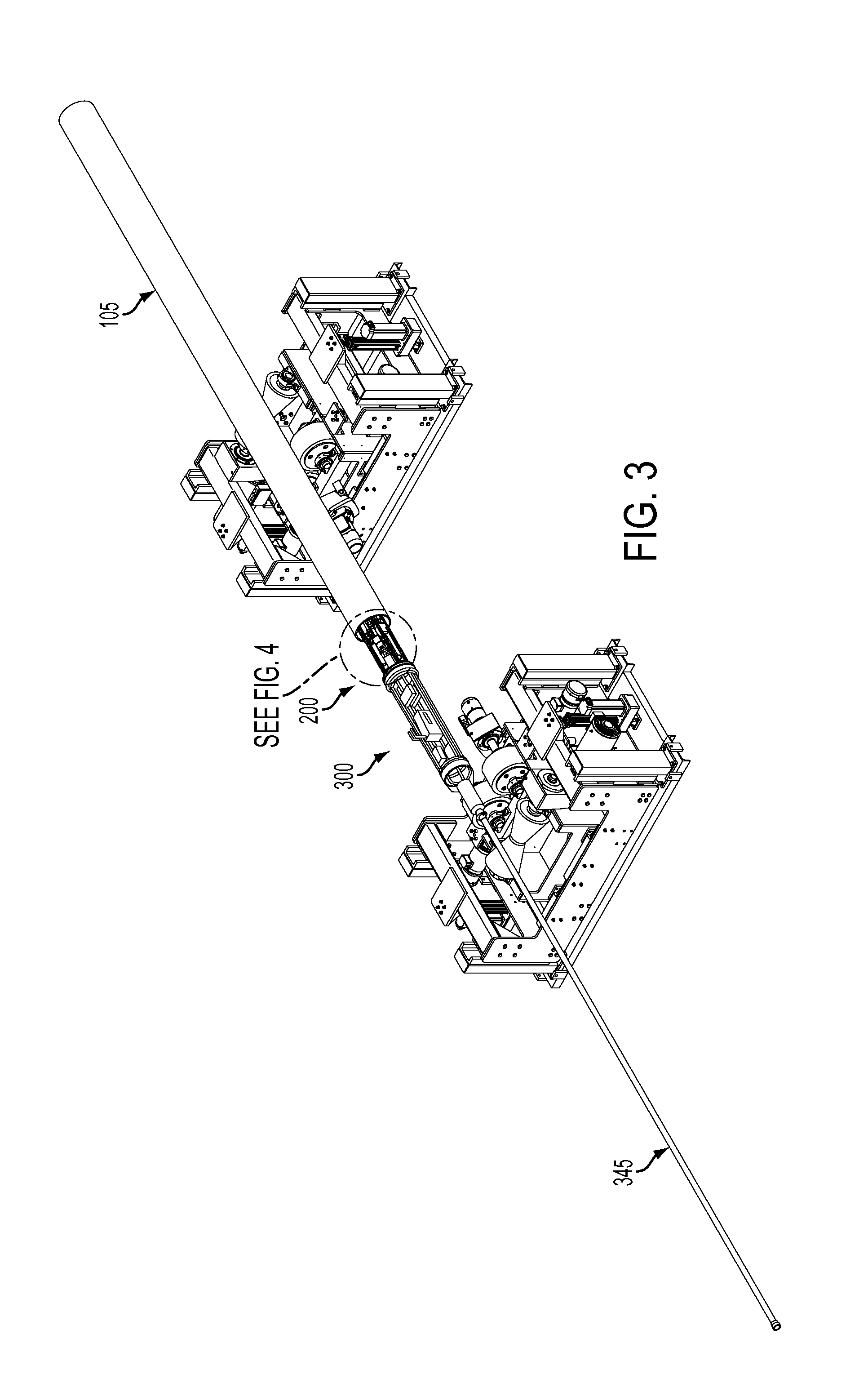
[0026]Referring to FIGS. 1-3, the system for welding pipeline segments together is described as follows. FIG. 1 shows an external alignment mechanism 10A and 10B which is capable of supporting, positioning, and repositioning multiple lengths of pipeline. Each mechanism 10A and 10B may include supports (e.g., rollers) upon which a length of pipeline may be supported. A longitudinal roller 12 moveably supports pipeline segment 105 such that segment 105 may be repositioned along its longitudinal direction defined by arrow A. In addition, rotational rollers 14 are rotatable about an axis parallel to axis A-A of support segment 105 on either side of segment 105 enabling them to rotate or adjust the angular orientation of segment 105 about axis A-A. External alignment mechanism 10 is able to automatically manipulate multiple segments into various positions and orientations via motors, hydraulics, etc. For example the segments may be raised, lowered, rotated, tilted, pivoted, etc.

[0027]As ...


PUM

PropertyMeasurementUnit
structureaaaaaaaaaa
circumferenceaaaaaaaaaa
degrees of freedomaaaaaaaaaa

Abstract

The present invention is directed to a system for welding together segments of a pipeline. The system includes an external alignment mechanism for externally supporting and manipulating the orientation of pipe segments in order to align relative segments. The system also includes an internal welding mechanism for applying a weld to an interior face joint of the two abutted pipe segments. The internal welding mechanism including a torch for applying a weld, a laser for tracking the weld profile and guiding an articulating head of the torch, and a camera for visually inspecting the weld after the weld is applied.

Description

CROSS-REFERENCE TO RELATED APPLICATIONS[0001]This application claims priority, under 35 U.S.C. §119(a)-(d), to U.S. Provisional application 61 / 826628, filed May 23, 2013, the contents of which are incorporated herein by reference in its entirety.FIELD OF THE INVENTION[0002]The present invention is directed to a system for aligning and connecting two pipe segments together by welding.BACKGROUND OF THE INVENTION[0003]Conventional internal welders frequently include internal alignment mechanisms that expand radially outward to contact the interior of the pipe. Alignment of the two pipe segments is accomplished from inside when extension members of a central member contact the interior of the pipe relatively close to the pipe segment joint faces on either side of the joint as shown in U.S. Pat. Nos. 3,461,264; 3,009,048; 3,551,636; 3,612,808 and GB 1261814 (which is each incorporated herein by reference in its entirety). In order to weld the joint, the structure of the expander must all...

Claims


Application Information

Patent Timeline
Patent Type & Authority Applications(United States)
IPC IPC(8): B23K9/028B23K37/02B23K37/053
CPCB23K9/0284B23K37/0276B23K37/0533B23K9/0286B23K37/0531B23K9/0956B23K9/1274B23K2101/10B23K37/053
Inventor RAJAGOPALAN, SHANKARMALLICK, SIDDHARTHBOUCHE, JOSE C.
Owner CRC EVANS PIPELINE INT INC
Why Eureka
Try Eureka