Functional uterine manipulator

a uterine manipulator and functional technology, applied in the field of uterine manipulators, can solve the problems drawbacks of current uterine manipulators, loss of pneumoperitoneum,

Active Publication Date: 2014-12-04
THE BRIGHAM & WOMEN S HOSPITAL INC
View PDF17 Cites 44 Cited by
  • Summary
  • Abstract
  • Description
  • Claims
  • Application Information

AI Technical Summary

Problems solved by technology

Current uterine manipulators can present drawbacks in certain situations.
In other cases, attempting to rotate the shaft can cause the occluder to slide along the shaft and disengage from the vaginal wall, resulting in a loss of pneumoperitoneum.
In addition, current uterine manipulators only serve to provide guidance for detaching the uterus and the cervix from the vagina via laparoscopic tools.

Method used


Image

  • Functional uterine manipulator
  • Functional uterine manipulator
  • Functional uterine manipulator

Examples


Embodiment Construction

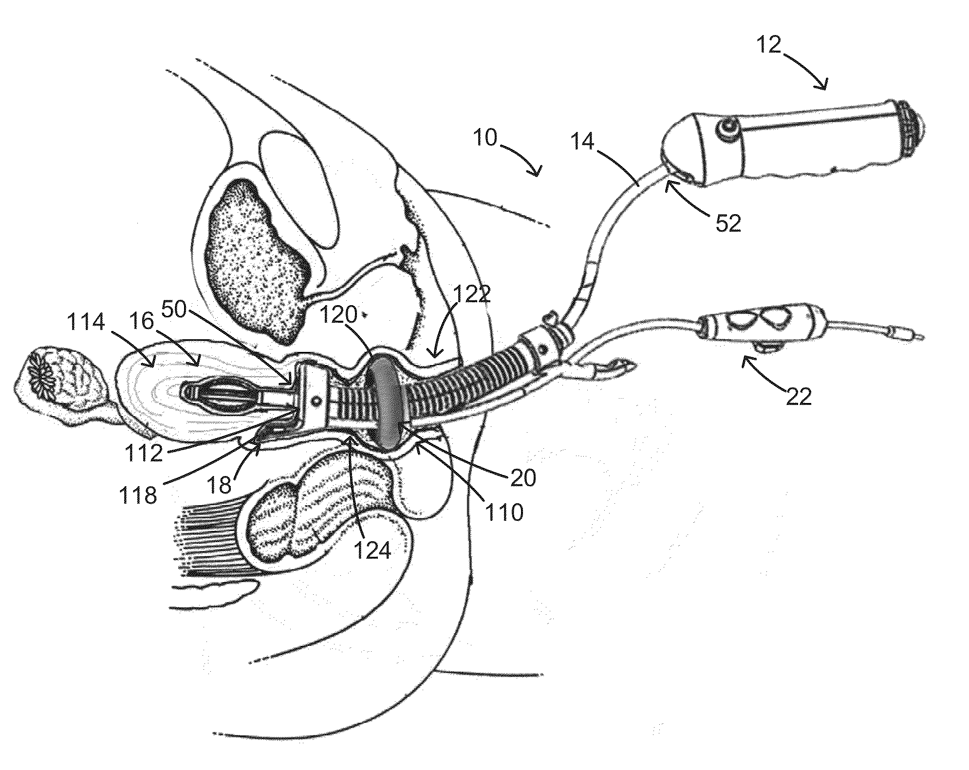
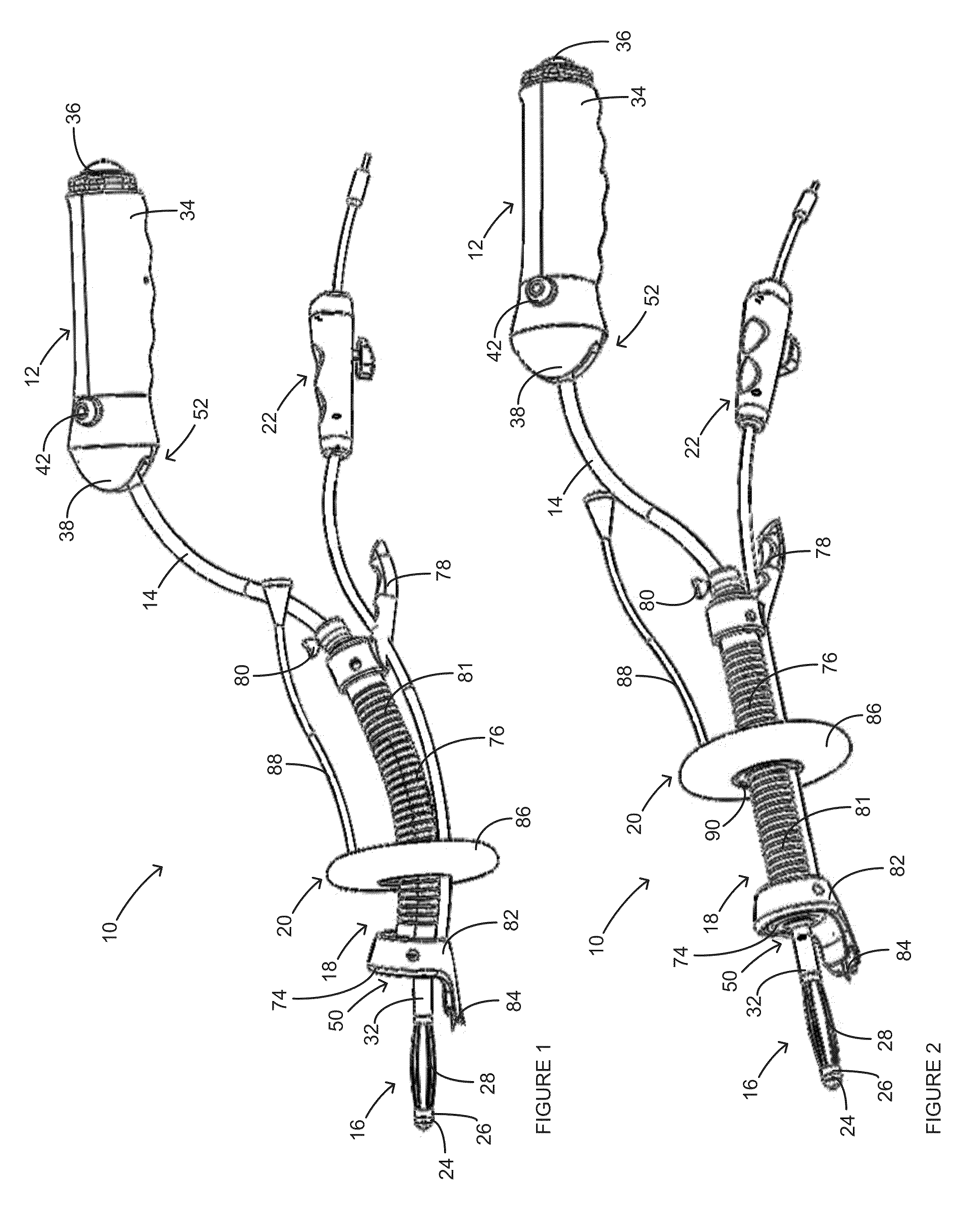
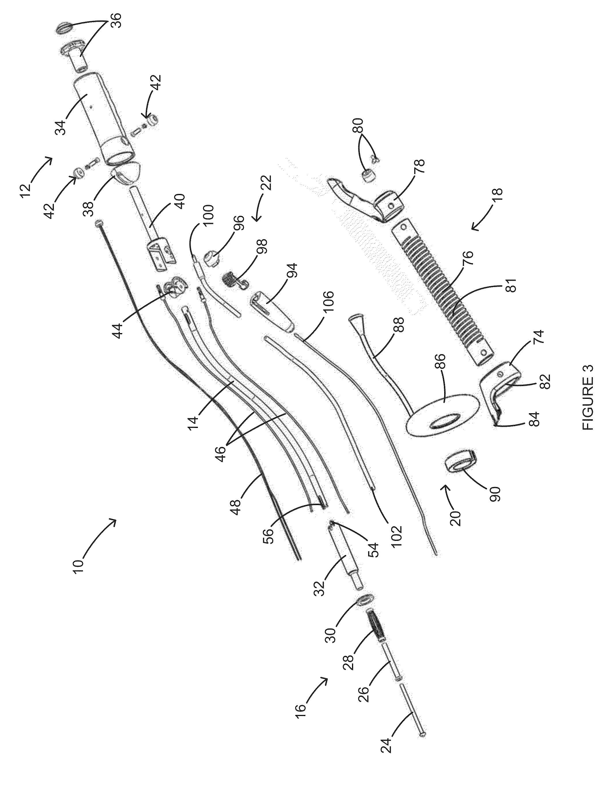
[0026]FIGS. 1 and 2 illustrate a functional uterine manipulator 10, according to the invention, for use in vaginal hysterectomies, laparoscopically assisted vaginal hysterectomies, and / or other pelvic procedures. The uterine manipulator 10 can include a handle 12, a shaft 14, a tip assembly 16, a cutting assembly 18, a pneumooccluder 20, and an electrical connector assembly 22. During use, the uterine manipulator 10 can be inserted into a patient's vagina 110, as shown in FIG. 12A, and then guided past the cervix 112 and into the uterus 114, as shown in FIG. 12B, using the handle 12. More specifically, as shown in FIGS. 12B and 12C, when the uterine manipulator 10 is inserted, the tip assembly 16 can be positioned in the uterus 114, the cutting assembly 18 can be positioned adjacent to the vaginal fornix 118 and can press against the cervix 112, and the pneumooccluder 20 can be positioned inside the vagina 110.

[0027]As shown in FIG. 3, the tip assembly 16 can include an expansion ti...


PUM


Abstract

A uterine manipulator operable to detach the uterus and cervix from the vagina. The uterine manipulator includes a shaft with a first end and a second end, a handle coupled to the first end, and a tip assembly coupled to the second end and adapted for insertion into the uterus. The uterine manipulator also includes a cutting assembly coupled around the shaft and adapted to receive the cervix when the tip assembly is inserted into the uterus. The cutting assembly includes a cup portion and a cutter wire. The cup portion is configured to be positioned at a juncture between the cervix and the vagina and includes with two grooves around its circumference. The cutter wire is configured to be positioned between the two grooves when in a stored position, and then pulled from between the two grooves through tissue at the juncture to cut the tissue.

Description

CROSS-REFERENCE TO RELATED APPLICATIONS[0001]This application is a continuation-in-part of U.S. application Ser. No. 14 / 375,200, which is the National Stage of International Application No. PCT / US2012 / 065584, filed Nov. 16, 2012, which claims the benefit of U.S. Provisional Application No. 61 / 592,125, filed Jan. 30, 2012, the disclosures of which are hereby incorporated by reference in their entirety for all purposes.BACKGROUND OF THE INVENTION[0002]The present invention relates generally to uterine manipulators and methods of using a uterine manipulator for detaching the uterus and cervix from the vagina.[0003]Uterine manipulators are conventionally used as aids in laparoscopic hysterectomies to mobilize and position the uterus, to provide better visualization of the vagina and the cervix for facilitating their separation, and to remove the uterus after colpotomy is performed. Basic uterine manipulators include a handle, a shaft, an inflatable balloon, and a cervical stop. The hand...

Claims


Application Information

Patent Timeline
Patent Type & Authority Applications(United States)
IPC IPC(8): A61B17/42
CPCA61B17/42A61B2017/4216A61B2017/4225A61B17/4241A61B34/70A61B17/32
Inventor EINARSSON, JON
Owner THE BRIGHAM & WOMEN S HOSPITAL INC
Why Eureka
Try Eureka