

Method for determining mechanical damage to a rotor blade of a wind turbine
- Summary
- Abstract
- Description
- Claims
- Application Information
AI Technical Summary
Benefits of technology
Problems solved by technology
Method used
Image

Examples
Example
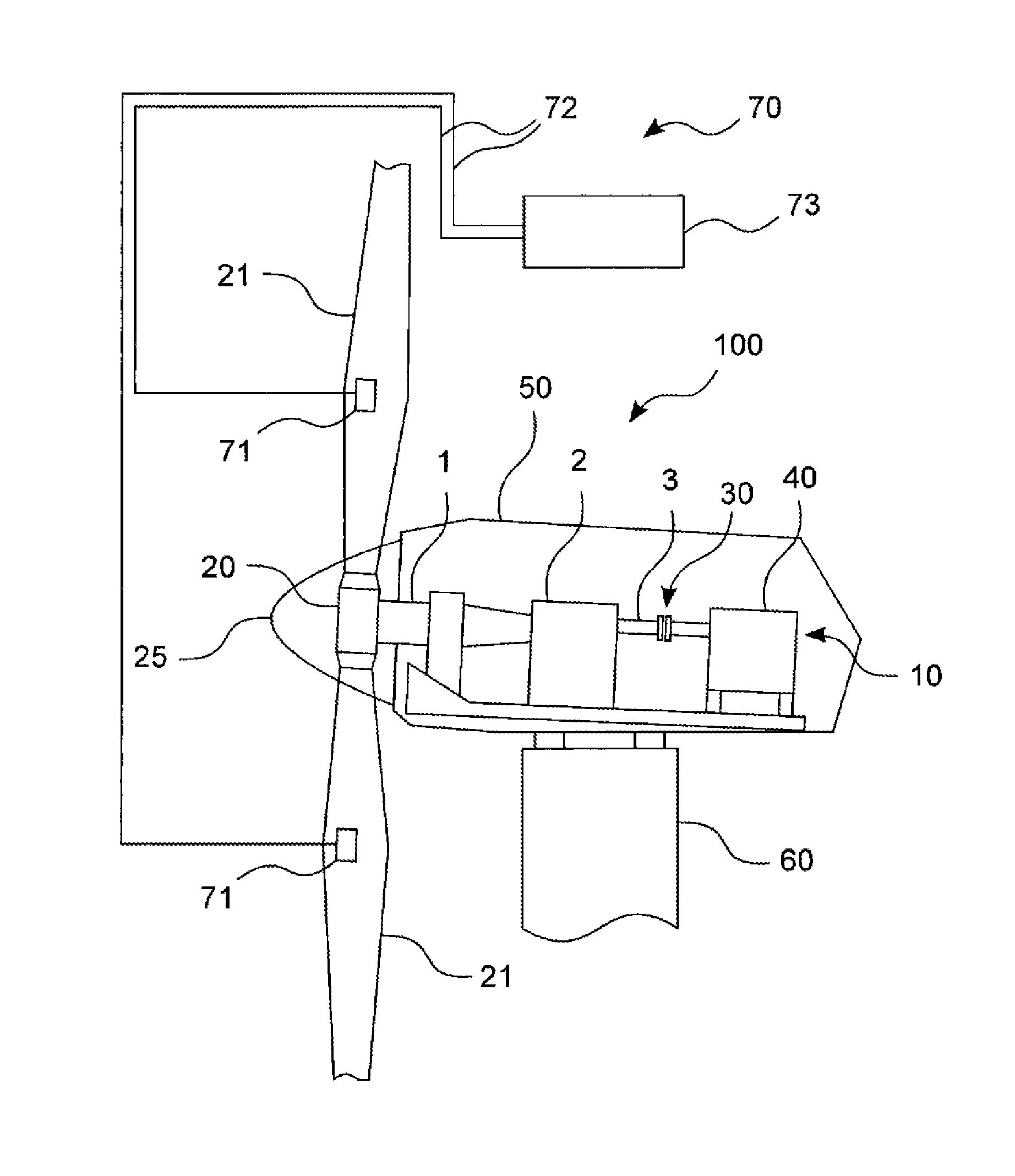
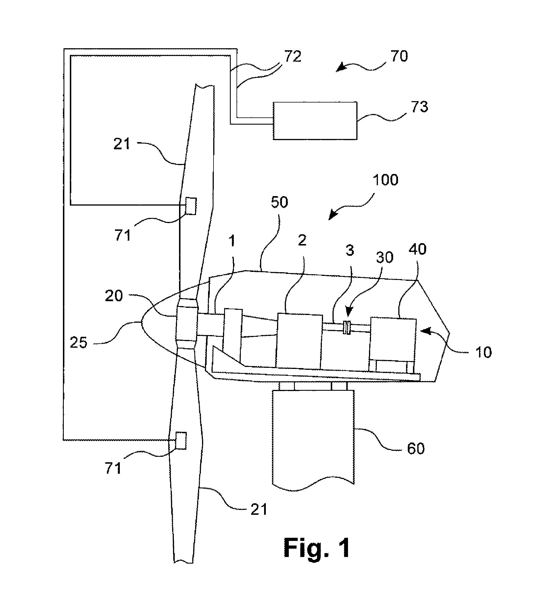
[0028]Represented in FIG. 1 is a longitudinal sectional view of a part of a wind turbine, which can be monitored by means of a method according to a particularly preferred embodiment of the invention. The wind turbine is denoted as a whole by 100, its drive train 10 being denoted by 10.
[0029]The drive train 10 shown is composed substantially of a main shaft 1, to which a rotor 20 is attached, and of a gearbox 2 and a generator shaft 3. The gearbox 24 may be, for example, a three-stage gearbox normally used in wind turbines. The main shaft 1 is connected by force closure to the rotor 20, for example a rotating blade rotor. The generator shaft 3 may be connected to a generator 40 via a clutch 30. The main shaft 1, the gearbox 2, the generator shaft 3 and the generator 40 are supported with corresponding means, enclosed in a housing 50 and mounted on a tower 60. Two rotor blades 21, represented partially, are shown on the rotor 20. Rotors normally used in wind turbines have, for exampl...
PUM
 Abstract
Description
Claims
Application Information