Multiple insert fence system

Inactive Publication Date: 2015-01-08
MARAVENTANO ROBERT EMANUEL
View PDF13 Cites 0 Cited by
  • Summary
  • Abstract
  • Description
  • Claims
  • Application Information

AI Technical Summary

Benefits of technology

The invention is about a system for improving safety and accuracy when using powered cutting tools, specifically mitre saws. The system includes an auxiliary fence that can be added to the saw to provide support and a clear reference point for the operator. The fence can be adjusted to different sizes of the saw and can help prevent the blade from hitting the workpiece too hard, resulting in a partial kerf cut. The system also includes a laser product that visually delineates a cutting reference for the operator and a blade housing with through-holes to close the large gaps between the blade and the saw. Overall, the system improves safety and accuracy when using mitre saws and makes the cutting process more efficient.

Problems solved by technology

Distinct disadvantages result from having a gap overly large in relation to a generally ⅛″ thick saw blade.
One disadvantage, dangerous in nature is evident when shorter sections of off-cut material result from a given cutting operation.
Often after a workpiece is severed a shorter off-cut section, having not sufficient back-up is pulled by the still spinning blade, smashes up within a blade housing and is uncontrollably thrown.
A further disadvantage of having overly large gaps pertains to quality of cut.
As cuts are made and the blade exits the workpiece, solid wood fibres tend to tear-out, and in composite wood products, chipping occurs.
Difficulty in positioning a workpiece so as to be cut to a desired length also arises, owing to an overly large gap.
Sufficient workpiece support throughout the cutting-area still is not addressed.
Mitre saws being of various sizes have respective limitations in maximum dimensions of a workpiece which they are capable of severing completely.
As a result, the cutting-area of the auxiliary fence itself becomes enlarged, and effectively destroyed.
This causes further unnecessary danger as chunks of the auxiliary fence itself break-out, are pulled-in to smash-up within the body of the mitre saw, and are uncontrollably thrown.
Eventually, it becomes necessary to replace the entire essentially useless auxiliary fence.
This involves needless waste of material, time, and labor to construct and change-over an entire fresh auxiliary fence, the benefits of which again, will be only temporary.
Although they correctly recite a need to reduce an opening in such a fence to a narrow gap, their fence is not readily directed at mitre saws.
Providing clearance for the saw blade path has still resulted in gaps overly large relative to a generally ⅛″ thick blade.
Still, however, relatively large gaps are evident in providing clearance for the blade.

Method used


Image

  • Multiple insert fence system
  • Multiple insert fence system
  • Multiple insert fence system

Examples


Embodiment Construction

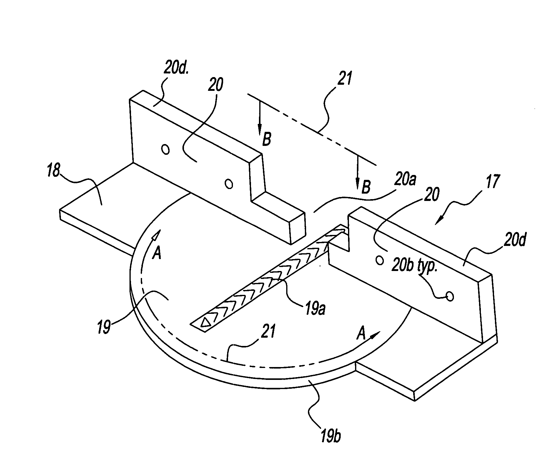
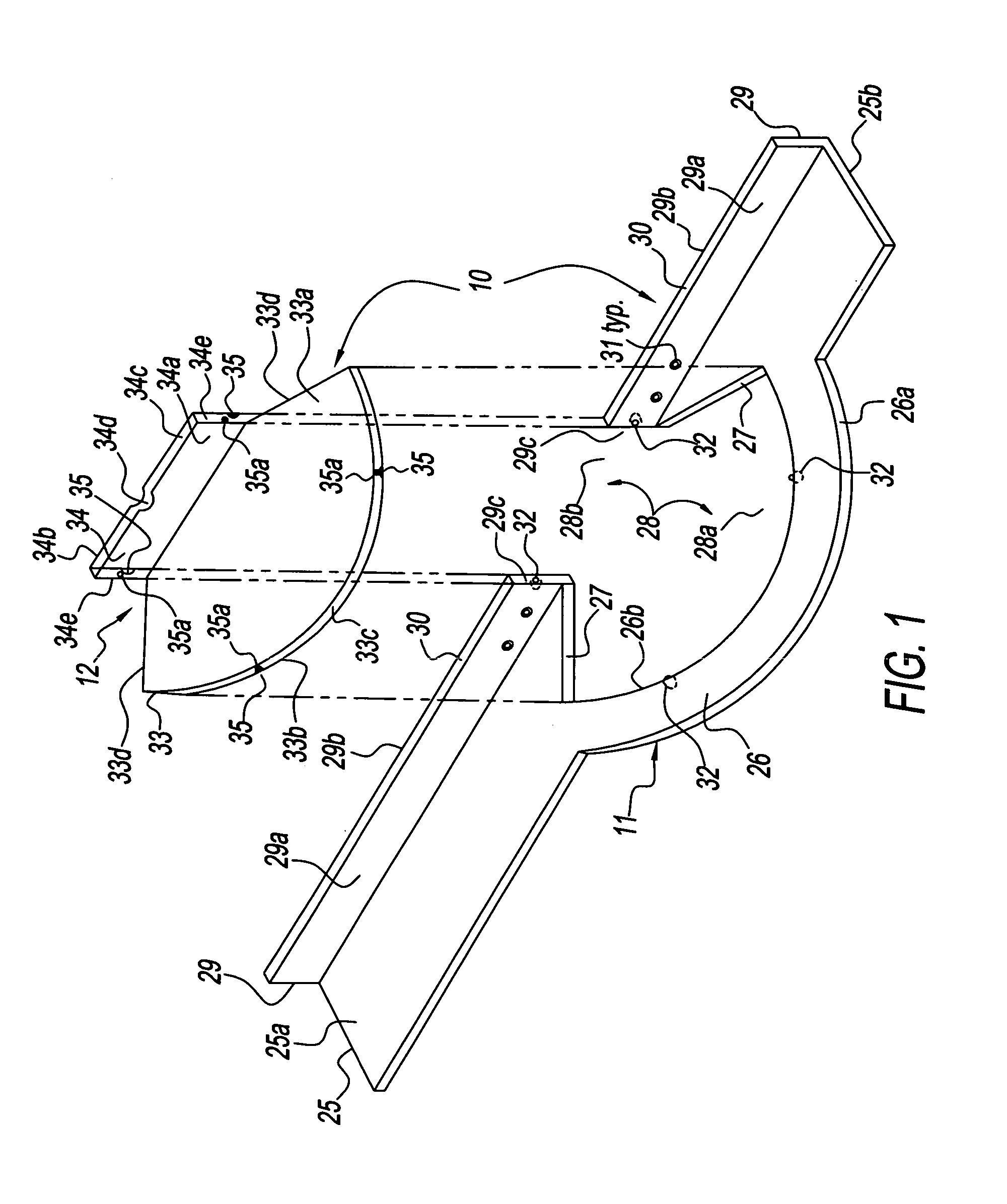
[0137]A preferred embodiment of the present invention will be herein described. It is intended to be exemplary and not limiting. It relates specifically to mitre saws and can easily be dimensionally adapted / modified for use with a variety of sizes and models of mitre saws available. By way of providing a single yet non-limiting set of approximate, exemplary dimensions, those relevant to a typical 10″ mitre saw will be herein recited.

[0138]Similarly, a variety of raw materials possess the appropriate rigidity and durability necessary for manufacture of such a system herein described. These would include: wood, plywood, composite wood products, plastics, composite plastics, metal, alloys, or any combination thereof.

[0139]Accordingly, by way of simplification and not limitation, the system will be herein described as being constructed of approximately ⅝″ thick baltic birch plywood, and utilizing common spring-loaded ball-catches which are of metal. Various thickness' of baltic birch pl...


PUM

PropertyMeasurementUnit
Angleaaaaaaaaaa
Thicknessaaaaaaaaaa
Angleaaaaaaaaaa

Abstract

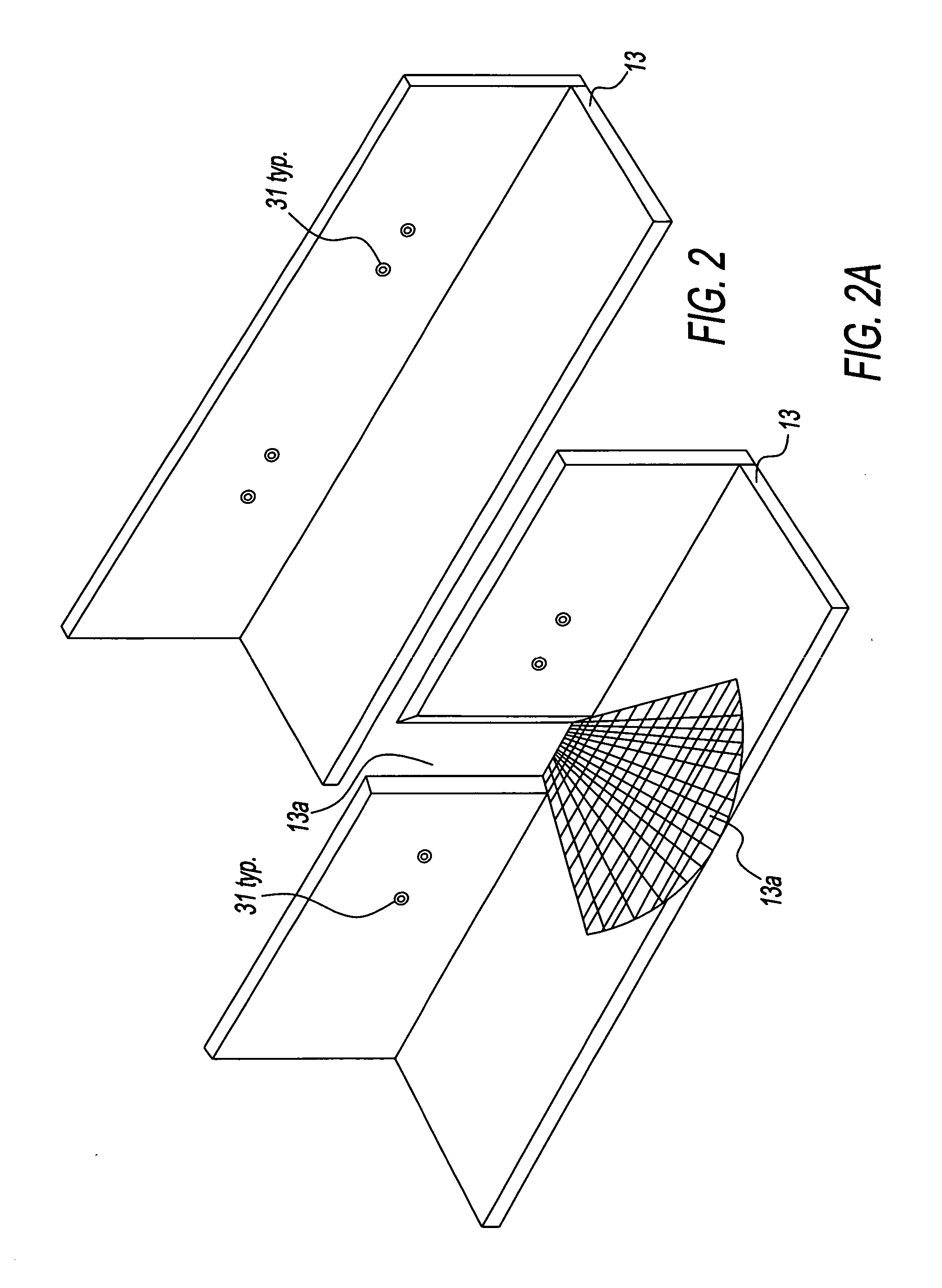
An auxiliary fence system which mounts on a mitre saw, for accommodating the cutting of material at each selectively of the various angles available on the mitre saw. There is provided a longitudinally extending stationary fence-frame having a generally L-shaped cross-section. The fence-frame overlays a stock table, and vertical back-fence of the mitre saw. Bolts secure the fence-frame to the stock vertical back-fence utilizing through-holes with counter-bores disposed along a vertical back-fence portion of the fence-frame. These through-holes having counter-bores, locationally correspond with through-holes disposed along the stock vertical back-fence of the mitre saw. The fence-frame further includes an aperture, being generally centered about a blade of the mitre saw. The fence system includes multiple angle-dedicated inserts, each selectively of which operatively engage and removably secure within the aperture. There are then formed smooth, continuous surfaces, in the horizontal, and vertical planes, against which material to be cut is placed, and supported. In operation, a blades-width partial kerf-cut is sustained within each selectively of the angle-dedicated inserts. This partial cut thereafter delineates a precise and reusable cutting-reference for a selected angle.

Description

BACKGROUND[0001]1. Field of Invention[0002]The invention relates generally to powered cutting tools of the type having a circular cutting blade as their respective cutting element, and more specifically to an auxiliary fence system which overlays the body of a stock mitre saw.[0003]2. Discussion of Prior-Art[0004]Powered cutting tools of the type having a circular cutting-blade employ one or more of integral or stock, and or end-user installed auxiliary fence(s). These fences are of varied configuration and intended purpose. One essential purpose is provision of rigid physical structure against which a workpiece is placed. This offers support or back-up to material being cut. As herein interchangably referred to, material being cut is a workpiece, and exemplary shorter off-cut sections result from cutting operations which sever workpieces.[0005]As different available blade dispositions including height, angle or mitre, bevel and combinations thereof are set and utilized, a cutting-r...

Claims


Application Information

Patent Timeline
IPC IPC(8): B23D45/04B23D47/04
CPCB23D47/04B23D45/04B23D47/025B27B27/00Y10T83/762
Inventor MARAVENTANO, ROBERT EMANUEL
Owner MARAVENTANO ROBERT EMANUEL
Why Eureka
Try Eureka