Printing device, printhead, and method of positioning print media in a printer

Active Publication Date: 2015-01-08
SEIKO EPSON CORP
View PDF1 Cites 4 Cited by
  • Summary
  • Abstract
  • Description
  • Claims
  • Application Information

AI Technical Summary

Benefits of technology

[0010]The present invention is directed to a printing device and a method of positioning media in the printing device that can accurately compens

Problems solved by technology

Printers of this type can typically convey the print medium in both forward and reverse directions, but when the conveyance direction is changed to the opposite direction, the position can shift or slip due to backlash.
This type of printer enters a standby mode while the print medium is held between the printhead and platen roller, and a long time can pass with the print medium held pressed against the printhead.
For example, slipping can occur when conveying media in a specific conveyance direction due to the construction of the conveyance mechanism that conveys the print media.
Because this deviation is not necessarily the same every time the conveyance direction changes and backlash occurs, accurate measurement is difficult.
Because the print medium cannot be reversed in this configuration, the print medium may be conveyed a greater distance to reach the desired indexing position, and waste increases.
If there is variation in parts of the printhead, such as positioning error or twisting of the head unit, movement of the printhead may be limited by the stops and pressure may be uneven when the printhead is pushed to the platen roller, print quality may therefore drop

Method used


Image

  • Printing device, printhead, and method of positioning print media in a printer
  • Printing device, printhead, and method of positioning print media in a printer
  • Printing device, printhead, and method of positioning print media in a printer

Examples


embodiment 1

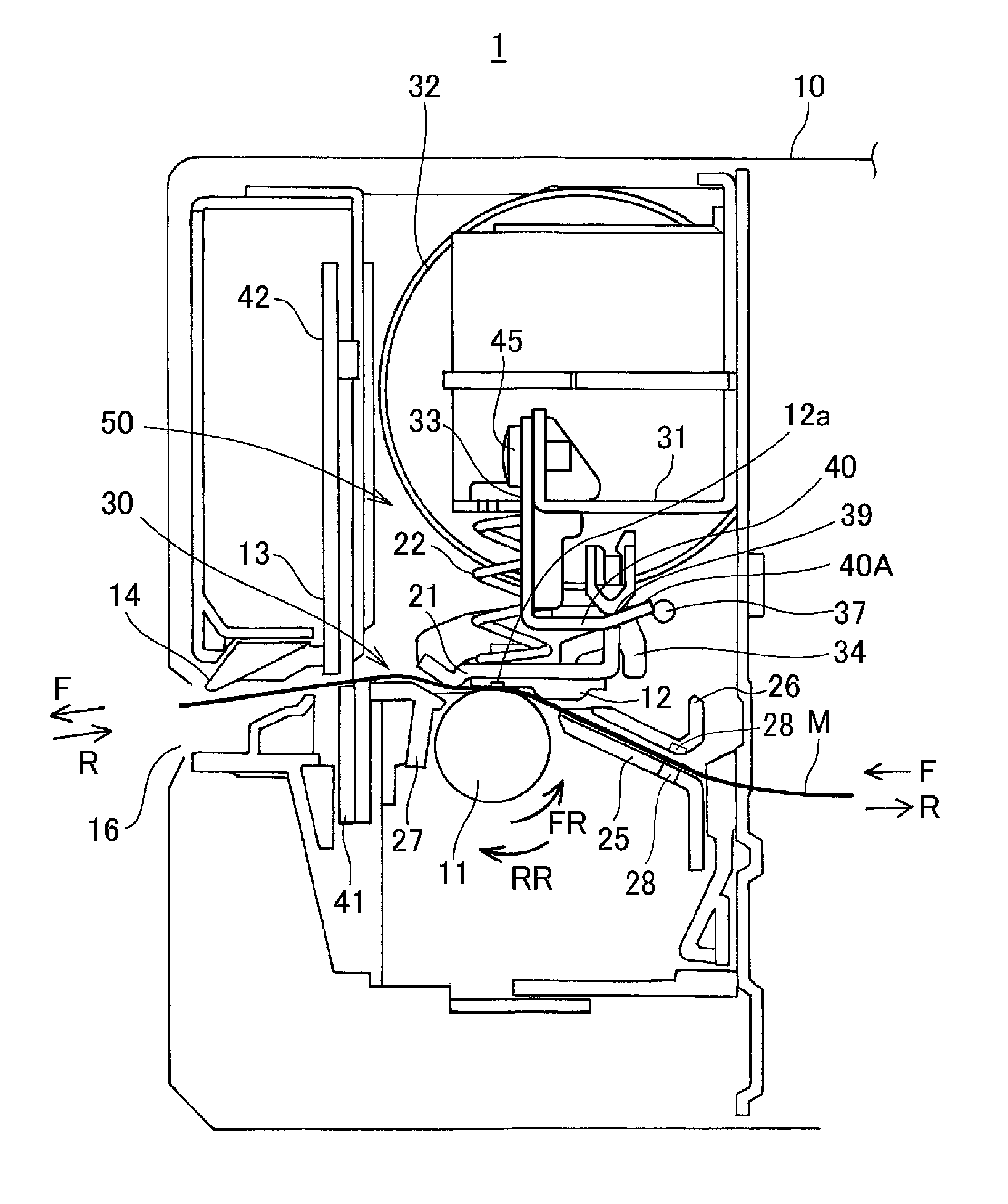
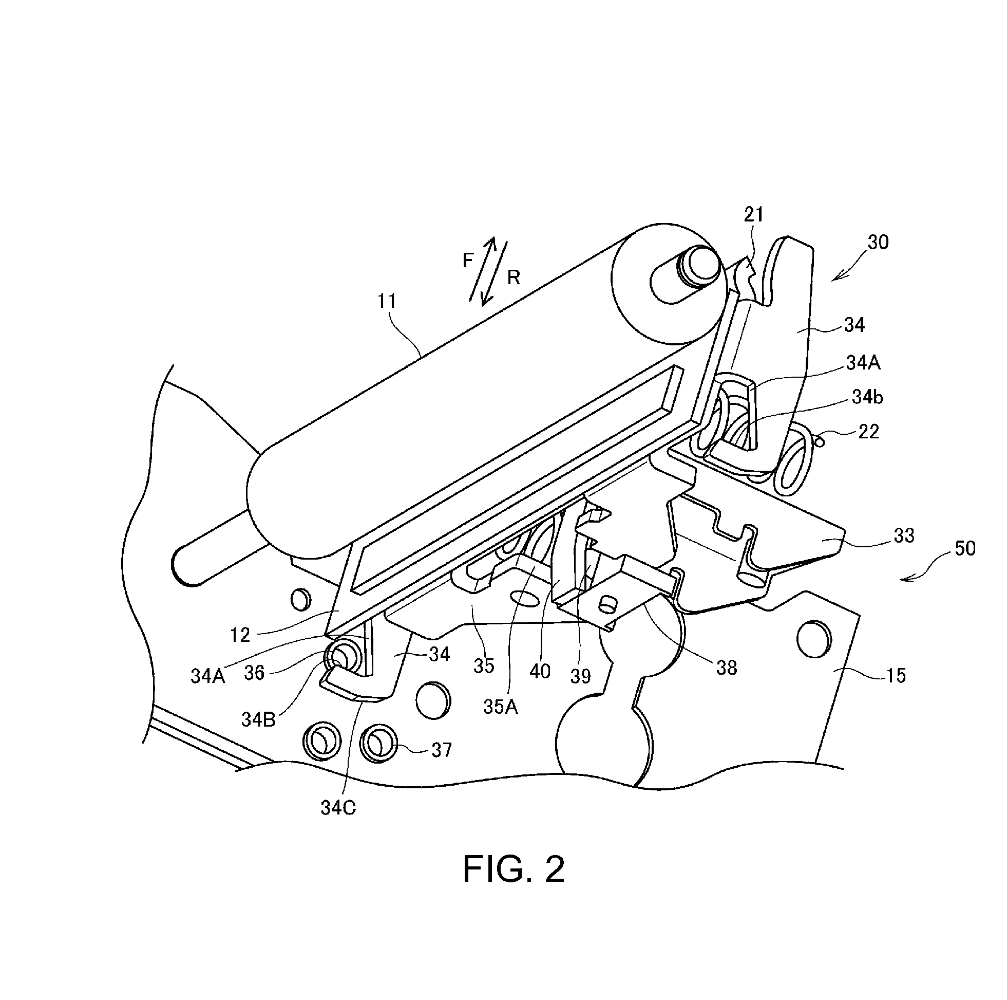
[0068]FIG. 1 is a side section view showing ma in parts in the configuration of a printer 1 (printing device) according to a first embodiment of the invention, and FIG. 2 is an oblique view showing the relative positions of the platen roller 11 and printhead 30. FIG. 1 is a side view of the configuration inside the case 10 of the printer 1. The left side of the printer as shown in FIG. 1 is the front of the printer 1.

[0069]The printer 1 has functional units including the platen roller 11, the printhead 30, an automatic cutter 13, and a manual cutter 14 inside a basically box-shaped case 10. The printer 1 conveys continuous paper M used as the print medium by rotation of the platen roller 11, and prints text or images on the printing surface of the continuous paper M with the printhead 30. The printed continuous paper M is then discharged from a paper exit 16 open in the front of the case 10.

[0070]The continuous paper M is held in a paper storage unit (not shown in the figure) config...

embodiment 2

[0109]A second embodiment of the invention is described next with reference to FIG. 6 to FIG. 8. Note that like parts in this and the printer 1 according to the first embodiment described above are identified by like reference numerals, and further description thereof is omitted.

[0110]FIG. 6 is a side section, view showing main parts in the configuration of a printer 5 (printing device) according to this embodiment of the invention. FIG. 6 shows a side view of the configuration inside the case 10 of the printer 5. The left side in FIG. 6 is the front of the printer 5.

[0111]Similarly to printer 1, this printer 5 has functional units including the platen roller 11, a printhead 60, an automatic cutter 13, and a manual cutter 14 inside a basically box-shaped case 10. The printer 5 conveys continuous paper M used as the print medium by rotation of the platen roller 11, and prints text or images on the printing surface of the continuous paper M with the printhead 60. The printed continuou...

embodiment 3

[0121]In the printer 1 according to the first embodiment and the printer 5 according to the second embodiment of the invention, the continuous paper M sticking to the head unit 12 can be easily resolved by rotating the platen roller 11 in the reverse direction (RR). In other words, when the platen roller 11 turns in the reverse direction (RR) to unstick the medium, the head unit 12 moves in the direction away from the platen roller 11, and the adhesive force weakens. Slipping therefore occurs more easily when conveying the continuous paper M in reverse (R) than when conveying the continuous paper M forward (F) because the adhesive force on the continuous paper M is lower. As a result, the amount that the continuous paper M is actually conveyed (moved) will therefore differ when the continuous paper M is conveyed forward (F) and when the continuous paper H is conveyed in reverse (R) even if the platen roller 11 turns the same amount. In other words, the conveyance distance of the con...


PUM


Abstract

A printing device and a positioning method of a printing device can accurately compensate for deviation between the intended conveyance of the print medium, and the actual movement of the print medium when conveyed. A printer 5 has a conveyance motor 32 that can selectively convey print media forward and reverse; and a control unit 101 controls the conveyance motor 32 to convey the print medium. The control unit 101 executes a specific sequence, and calculates the difference in the conveyance amount of the print medium in each direction when the conveyance unit is operated the same amount in both directions. This sequence includes changing from forward to reverse and from reverse to forward the same number of times, a first conveyance of the continuous paper M forward or reverse, and a second conveyance in the opposite direction as the first conveyance.

Description

[0001]Priority is claimed under 35 U.S.C. §119 to Japanese Application nos. 2013-140362 filed on July 4 and 2013-130017 filed on August 30, which are hereby incorporated by reference in their entirety.BACKGROUND[0002]1. Technical Field[0003]The present invention relates to a printing device, a printhead, and a method of positioning a print medium in the printing device.[0004]2. Related Art[0005]Printers that detect an indexing mark such as a notch or a position recognition marker disposed to the print medium and position the print medium based on the detected mark are known from the literature. See, for example, JP-A-2013-22861. The device taught in JP-A-2013-22861 detects the perforation or a slit formed between each page of a continuous medium such as fanfold paper or roll paper by an optical sensor disposed to the media conveyance path. After detection by the optical sensor, an operation for setting the position to cut a label after printing to the detected perforation, for examp...

Claims


Application Information

Patent Timeline
IPC IPC(8): B41J13/00
CPCB41J13/0009B41J2/32B41J11/42B41J11/46
Inventor ENDO, KATSUYUKI
Owner SEIKO EPSON CORP
Why Eureka
Try Eureka