Optical disk drive having a tilt compensator

a technology of optical disk drive and compensator, which is applied in the direction of digital signal error detection/correction, instruments, recording signal processing, etc., can solve the problems of not having preventing the tilt sensor from directly measuring the tilt angle, and the technique cannot have the advantage of general tilt actuator

Inactive Publication Date: 2003-09-25
NEC CORP
View PDF4 Cites 47 Cited by
  • Summary
  • Abstract
  • Description
  • Claims
  • Application Information

AI Technical Summary

Problems solved by technology

However, the techniques using the tilt actuator mechanism involve a tilt amount between the head carriage mounting thereon the tilt sensor and the objective lens, thereby preventing the tilt sensor from directly measuring the tilt angle.
Although there is some technique including a tilt sensor provided in the frame area of the objective lens which inclines together with the objective lens, this technique does not have the advantage of the general tilt actuator mechanisms that the movable part has a smaller thickness.
As to the technique using the pre-hit header, there is the problem that the optical disk may have no pre-hit header therein, or that the configuration of the pre-pit header is different between different optical disks to narrow the range of application of this technique thereto, even if the optical disks may have respective pre-pit headers.
As to the technique using the reproduced signal, there is the problem that the tilt angle cannot be measured with a higher accuracy due to the deteriorated signal sensitivity of the reproduced

Method used


Image

  • Optical disk drive having a tilt compensator
  • Optical disk drive having a tilt compensator
  • Optical disk drive having a tilt compensator

Examples


first embodiment

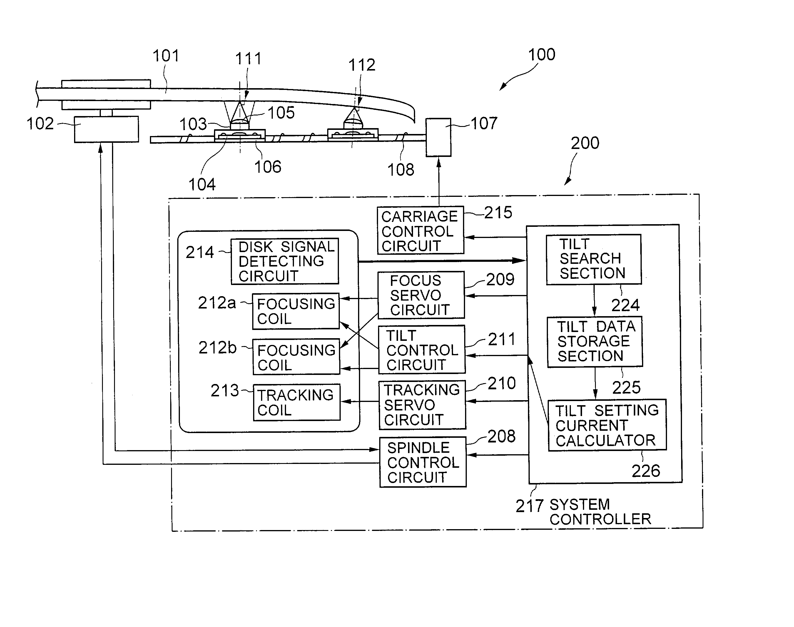
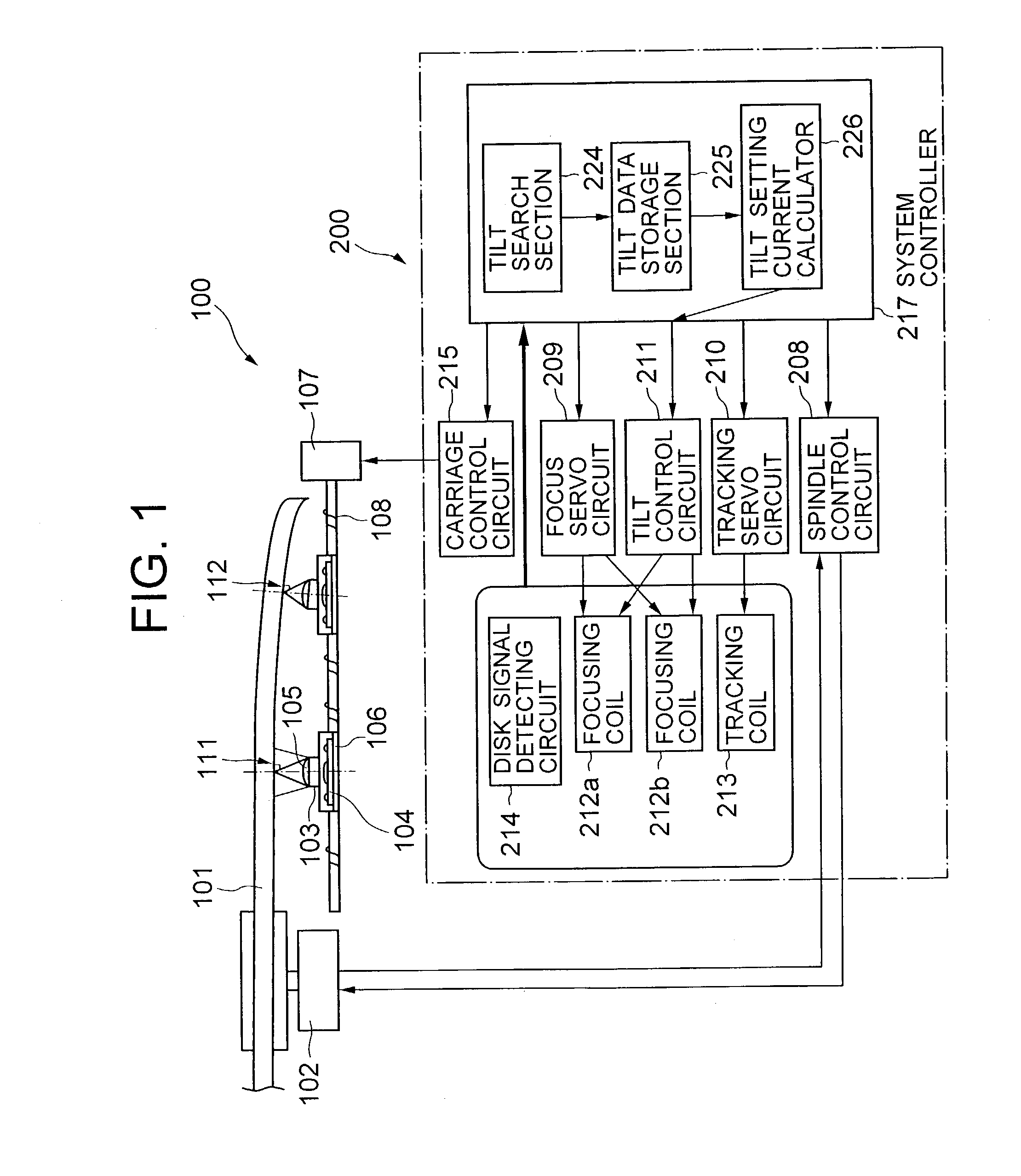
[0041] Referring to FIG. 1, an optical disk drive according to the present invention includes a disk drive section 100 and a drive control block 200. The disk drive section 100 includes a spindle motor 102, an optical head 103, a tilt sensor 104, an objective lens 105, a head carriage 106, a carriage motor 107 and a lead screw 108. The drive control block 200 includes a spindle control circuit 208, a focus servo circuit 209, a tracking servo circuit 210, a tilt control circuit 211, a pair of focusing coils 212a and 212b, a tracking coil 213, a disk signal detecting circuit 214, a carriage control circuit 215, and a system controller 217 including a tilt search section 224, a tilt data storage section 225 and a tilt-setting current calculator 226.

[0042] The spindle motor 102 rotates the optical disk 101 mounted on the disk drive section 100 at a specified rotational velocity. The head carriage 106 mounts thereon the optical head 103 and the tilt sensor 104 and moves them in the direc...

second embodiment

[0076] Referring to FIG. 8, a tilt compensator provided in an optical disk drive according to the present invention is similar to the tilt compensator shown in FIG. 1 except for a loop gain measurement circuit 227 provided in the present embodiment for controlling the tilt error by using the loop gain. The loop gain measurement circuit 227 provides a periodic disturbance to the tracking servo circuit 210 when the tracking servo circuit 210 is operating for a tracking control of the optical spot, and extracts the influence by the periodic disturbance from the detected tracking error signal.

[0077] The loop gain is obtained by measuring the magnitude of the signal component superposed on the tracking error signal by the periodic disturbance. More specifically, a lower frequency component is extracted by passing the detected tracking error signal through a band-pass filter, and detected by a level detector as a DC component among the components of the periodic disturbance.

[0078] Referri...


PUM


Abstract

A tilt compensator in an optical disk drive detects an optimum tilt setting of the objective lens with respect to a reference plane of the optical head, which allows the optical head to obtain an optimum characteristic of a disk signal at a specified radial position of an optical disk. The optimum tilt setting is corrected at a desired track of the optical disk by using a difference between a first tilt angle of the reference plane with respect to the optical disk measured at the specified radial position and a second tilt angle of the reference plane measured at a desire track of the optical disk. The disk signal is a RF signal, a jitter of the encoded RF signal, a tracking error signal or a wobble signal.

Description

[0001] (a) Field of the Invention[0002] The present invention relates to an optical disk drive having a tilt compensator and, more particularly, to an optical disk drive having a tilt compensator capable of correcting the tilt error between an optical disk and the optical axis of an objective lens used for radiating therethrough an optical spot onto the optical disk. The present invention also relates to a method for correcting a tilt error in an optical disk drive.[0003] (b) Description of the Related Art[0004] In general, an optical disk drive records and reproduces data on an optical disk by irradiating the optical disk with a laser beam from an optical pickup provided on a head carriage, which is capable of moving in the radial direction of the optical disk. If the optical axis of the objective lens provided on the optical pickup does not intersect the recording surface of the optical disk at an accurate right angle with respect thereto during recording / reproducing data on the o...

Claims


Application Information

Patent Timeline
IPC IPC(8): G11B7/09G11B7/095
CPCG11B7/0956G11B7/0945
Inventor IWAZAWA, NAOTOSHIYAMANAKA, YUTAKASUGAYA, SATOSHISHIMIZU, MOTOAKI
Owner NEC CORP
Why Eureka
Try Eureka