
Repeatable runout (RRO) compensation methods and apparatus for data storage devices

Inactive Publication Date: 2005-08-30
WESTERN DIGITAL TECH INC
View PDF21 Cites 49 Cited by
  • Summary
  • Abstract
  • Description
  • Claims
  • Application Information

AI Technical Summary

Benefits of technology

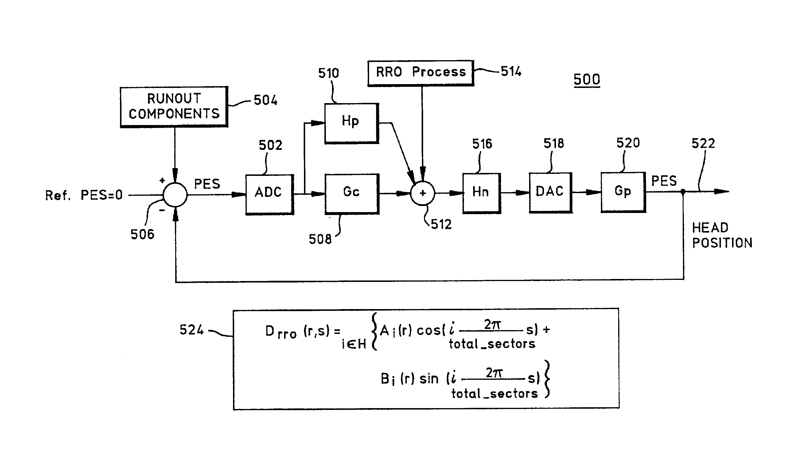
[0012]Repeatable runout (RRO) compensation methods and apparatus for data storage devices are disclosed. In one illustrative example, a method for use in reducing RRO error in a data storage device involves obtaining an RRO measurement for each track of a limited number of N disk tracks of a disk; characterizing the RRO measurement for each track with real and imaginary values by performing a discrete Fourier transform (DFT) calculation on each RRO measurement; performing a least-squares fit on the real values to identify a first set of (n+1) coefficients of an nth-order polynomial function which is a function of disk track r and representable in the form Ai(r)=anrn+a(n−1)r(n−1)+ . . . +a1r+a0; and performing a least-squares fit on the imaginary values to identify a second set of (n+1) coefficients of an nth-order polynomial function which is a function of disk track r and representable in the form Bi(r)=bnrn+b(n−1)r(n−1)+ . . . +b1r+b0. RRO compensation is performed by finding the estimated RRO error based on the relation DRRO(r, s)=Σi for all H{Ai(r)cos(i(s2π / total_sectors))+Bi(r)sin(i(s2π / total_sectors))}, where r is a track number; s is a sector number at track number r; i is an RRO harmonic number; H is a set of harmonics to be compensated; and total_sectors is a total number of sectors along track number r. Advantageously, RRO variations across the disk can be accurately compensated for with use of a small amount of memory.

Problems solved by technology

However, these approaches either require high cost manufacturing methods or increased track following voice coil motor (VCM) power.
However, the known prior art does not focus on a “global” learning scheme to compensate for RRO.
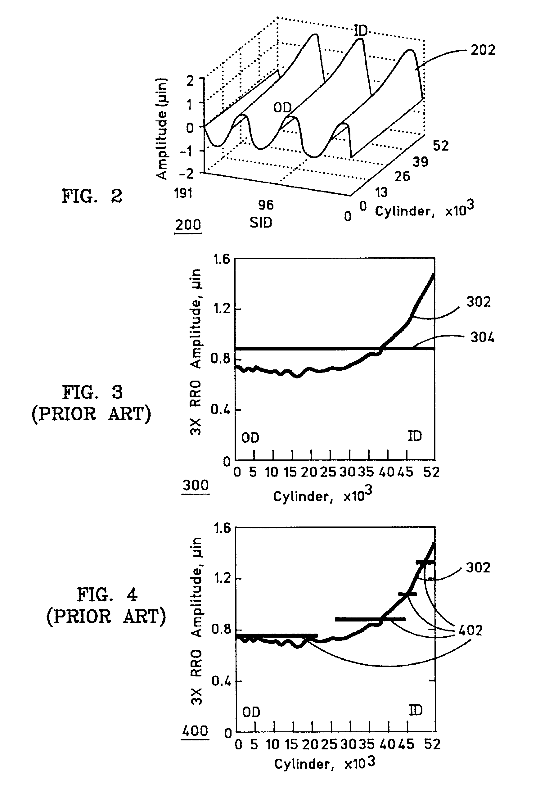
Some of the prior art techniques consider all disk tracks as a whole using an averaging function, but they do not take into account variations of amplitude and phase across the disk.
Other techniques focus on learning RRO characteristics of each track, but this requires a large amount of memory.

Method used


Image

  • Repeatable runout (RRO) compensation methods and apparatus for data storage devices
  • Repeatable runout (RRO) compensation methods and apparatus for data storage devices
  • Repeatable runout (RRO) compensation methods and apparatus for data storage devices

Examples


Embodiment Construction

[0024]The following description is the best embodiment presently contemplated for carrying out the present invention. This description is made for the purpose of illustrating the general principles of the present invention and is not meant to limit the inventive concepts claimed herein.

[0025]The Fourier Transform. A few centuries ago, a French mathematician named Fourier became famous for his theory that any waveform could be decomposed into a set of frequencies each having a unique amplitude and phase. Each one of these amplitude and phase components for a given frequency describes the displacement contribution at any point in time for that frequency. At any point in time, the combined displacement contributions of the entire set of frequencies will exactly describe the original waveform displacement measured at that point in time. The process of changing a “time domain” waveform into a “frequency domain” description is called a “Fourier transform”. The process of changing the freq...


PUM

PropertyMeasurementUnit
Erroraaaaaaaaaa
Orderaaaaaaaaaa

Abstract

In one illustrative example, a method for use in reducing Repeatable Run Out (RRO) error in a data storage device involves obtaining an RRO measurement for each track of a limited number of N disk tracks; characterizing the RRO measurement for each track with real and imaginary values by performing a discrete Fourier transform (DFT) calculation on each RRO measurement; performing a least-squares fit on all of the real values to identify a first set of (n+1) coefficients of an nth-order polynomial function which is a function of disk track r and representable in the form Ai(r)=anrn+a(n−1)r(n−1)+ . . . +a1r+a0; and performing a least-squares fit on all of the imaginary values to identify a second set of (n+1) coefficients of an nth-order polynomial function which is a function of disk track r and representable in the form Bi(r)=bnrn+b(n−1)r(n−1)+ . . . +b1r+b0. RRO compensation is performed based on the relation DRRO(r, s)=Σi for all H {Ai(r)cos(i(s2π / total_sectors))+Bi(r)sin(i(s2π / total_sectors))} where DRRO is the estimated RRO error; r is a track number; s is a sector number at track number r; i is an RRO harmonic number; H is a set of harmonics to be compensated; and total_sectors is a total number of sectors along track number r. Advantageously, RRO variations across the disk can be accurately compensated for with use of a small amount of memory.

Description

BACKGROUND OF THE INVENTION[0001]1. Field of the Invention[0002]This invention relates generally to servo control for data storage devices, and more particularly to repeatable runout (RRO) compensation methods and apparatus for servo-controlled data storage devices.[0003]2. Description of the Related Art[0004]High precision design is required for direct access storage devices (DASDs), such as disk drives. Without limiting operating vibration performance, the servo architecture of a DASD should be capable of providing a low positioning error for its read / write heads. In a track following mode, a disk actuator servo intends to minimize the head position error in the presence of both repeatable runout (RRO) and non-repeatable runout (NRRO) components in a position error signal (PES). The RRO component, which could be any repeated deviation from an ideal circular track due to, for example, mechanical tolerances or servo writing, may present itself as a repetitive disturbance having a fu...

Claims


Application Information

Patent Timeline
IPC IPC(8): G11B5/596G11B21/10G11B20/10
CPCG11B5/59627G11B5/59688F16L47/03H05B3/56F16L47/12
Inventor CHANG, JEN-YUANRALEY, JAY FRANCIS
Owner WESTERN DIGITAL TECH INC
Learn More