
Surgical device, surgical adapters for use between surgical handle assembly and surgical loading units, and methods of use

a technology for surgical devices and surgical adapters, which is applied in the field of hand-held powered surgical devices, surgical adapters and/or adapter assemblies, and can solve problems such as the incompatibility of loading units and/or handle assemblies of surgical devices

Active Publication Date: 2015-01-15
TYCO HEALTHCARE GRP LP
View PDF46 Cites 180 Cited by
  • Summary
  • Abstract
  • Description
  • Claims
  • Application Information

AI Technical Summary

Benefits of technology

The present disclosure is about a surgical device that includes a handle housing, an adapter, an elongated portion, a first drive element, and a second drive element. The device has two actuation mechanisms that can be used to perform different surgical functions. The first drive element is engaged with the first actuation mechanism and the second drive element is engaged with the second actuation mechanism. The first drive element causes the first drive element to move distally when the first actuation mechanism is rotated in one direction, and the second drive element causes the second drive element to move distally when the second actuation mechanism is rotated in the other direction. The device also has a fastener ejection mechanism that can be used to eject fasteners from the end effector of the device. The end effector can include a knife or a cartridge assembly with fasteners. The surgical device can be powered by a battery and has a compact design for easy handling and use in surgical procedures.

Problems solved by technology

As such, these loading units are not compatible with surgical devices and / or handle assemblies that use a rotary motion to deliver power or the like.

Method used


Image

  • Surgical device, surgical adapters for use between surgical handle assembly and surgical loading units, and methods of use
  • Surgical device, surgical adapters for use between surgical handle assembly and surgical loading units, and methods of use
  • Surgical device, surgical adapters for use between surgical handle assembly and surgical loading units, and methods of use

Examples


Embodiment Construction

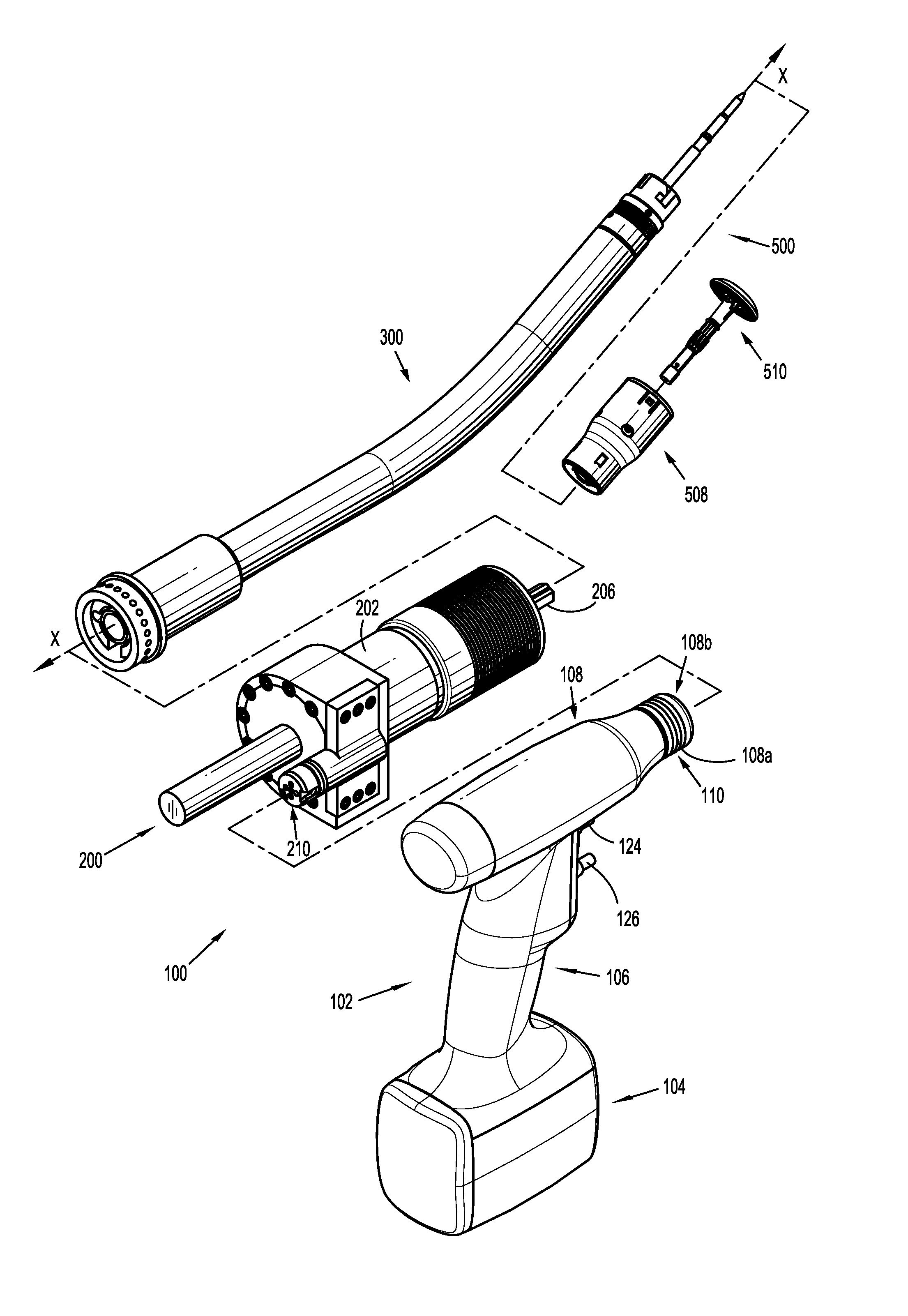
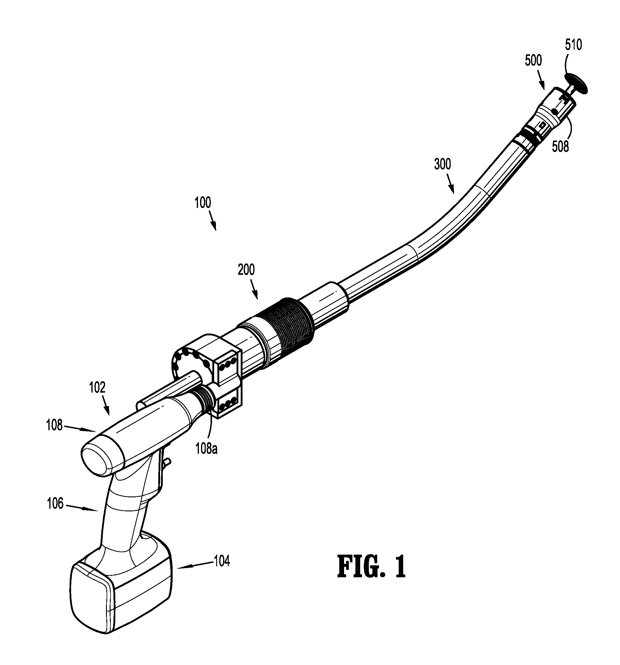
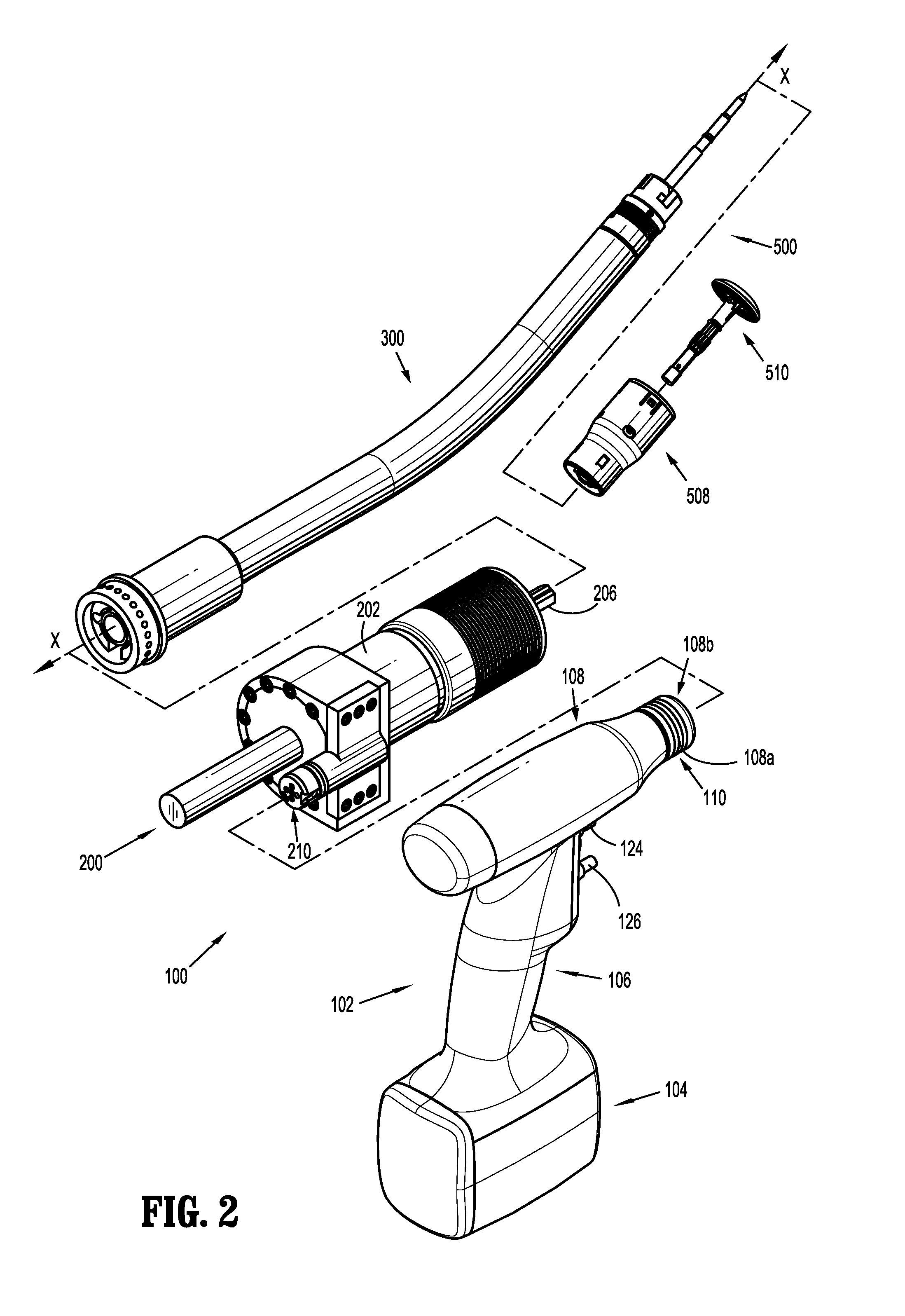
[0045]Embodiments of the presently disclosed surgical devices, and adapter assemblies for surgical devices and / or handle assemblies are described in detail with reference to the drawings, in which like reference numerals designate identical or corresponding elements in each of the several views. As used herein the term “distal” refers to that portion of the adapter assembly or surgical device, or component thereof, farther from the user, while the term “proximal” refers to that portion of the adapter assembly or surgical device, or component thereof, closer to the user.

[0046]A surgical device, in accordance with an embodiment of the present disclosure, is generally designated as 100, and is shown in the form of a powered hand held electromechanical instrument configured for selective attachment thereto of a plurality of different loading units that are each configured for actuation and manipulation by the powered hand held electromechanical surgical instrument.

[0047]As illustrated i...


PUM

PropertyMeasurementUnit
Diameteraaaaaaaaaa
Mechanical propertiesaaaaaaaaaa

Abstract

A surgical device comprising a handle housing, an adapter, an elongated portion, an end effector, a first drive element, and a second drive element is disclosed. The adapter includes a first drive assembly configured to mechanically engage a portion of a first actuation mechanism of the handle housing. The elongated portion is configured to extend distally from the adapter. The first drive element is disposed in mechanical cooperation with the first drive assembly. The second drive element is disposed in mechanical cooperation with the first drive assembly. Rotation of the first drive assembly in a first direction about the longitudinal axis causes distal translation of the first drive element. Rotation of the first drive assembly in a second direction about the longitudinal axis causes distal translation of the second drive element. The first direction is opposite from the second direction.

Description

BACKGROUND[0001]1. Technical Field[0002]The present disclosure relates to surgical devices and / or systems, surgical adapters and their methods of use. More specifically, the present disclosure relates to hand held powered surgical devices, surgical adapters and / or adapter assemblies for use between and for interconnecting the powered, rotating and / or articulating surgical device or handle assembly and a loading unit for clamping, cutting and / or stapling tissue.[0003]2. Background of Related Art[0004]Anastomosis is the surgical joining of separate hollow organ sections. Typically, an anastomosis procedure follows surgery in which a diseased or defective section of hollow tissue is removed and the remaining end sections are to be joined. Depending on the desired anastomosis procedure, the end sections may be joined by either circular, end-to-end or side-to-side organ reconstruction methods.[0005]In a circular anastomosis procedure, the two ends of the organ sections are joined by mean...

Claims


Application Information

Patent Timeline
IPC IPC(8): A61B17/115A61B17/3205
CPCA61B17/1155A61B17/3205A61B17/07207A61B2017/00398A61B2017/00389A61B2017/2903A61B2017/2925A61B2017/0046A61B17/115A61B2017/00473A61B17/072A61B2017/00477A61B2017/07257A61B2017/07285
Inventor WILLIAMS, JUSTINKASWER, CHRISTOPHER WILLIAM
Owner TYCO HEALTHCARE GRP LP
Learn More