Unlock instant, AI-driven research and patent intelligence for your innovation.

Differential-to-single-end converter

Active Publication Date: 2015-01-15
XUESHAN TECH INC
View PDF5 Cites 0 Cited by
  • Summary
  • Abstract
  • Description
  • Claims
  • Application Information

AI Technical Summary

Benefits of technology

The present invention provides a converter that converts a differential input signal to a single-end output signal. This converter includes four transistors and two current sources. The first and second transistors are driven by the differential input signal and have two conduction nodes each. The third and fourth transistors are driven by the differential input signal and connected in series with the first and second transistors. The current sources are connected in series with the third and fourth transistors and have a common control node. The second conduction node of the first transistor generates the single-end input signal. The method also includes controlling the current source based on the non-inverted signal, and conducting one of a discharging path and a charging path based on the inverted signal, and disconnecting the other path. This makes it possible to generate the single-end signal based on the logic value of the differential signal.

Problems solved by technology

Compared to one signal transmission line that a single-end signal requires, the design of the at least two signal transmission lines increases routing complexities and a pin count in an integrated circuit.

Method used


Image

  • Differential-to-single-end converter
  • Differential-to-single-end converter
  • Differential-to-single-end converter

Examples


Embodiment Construction

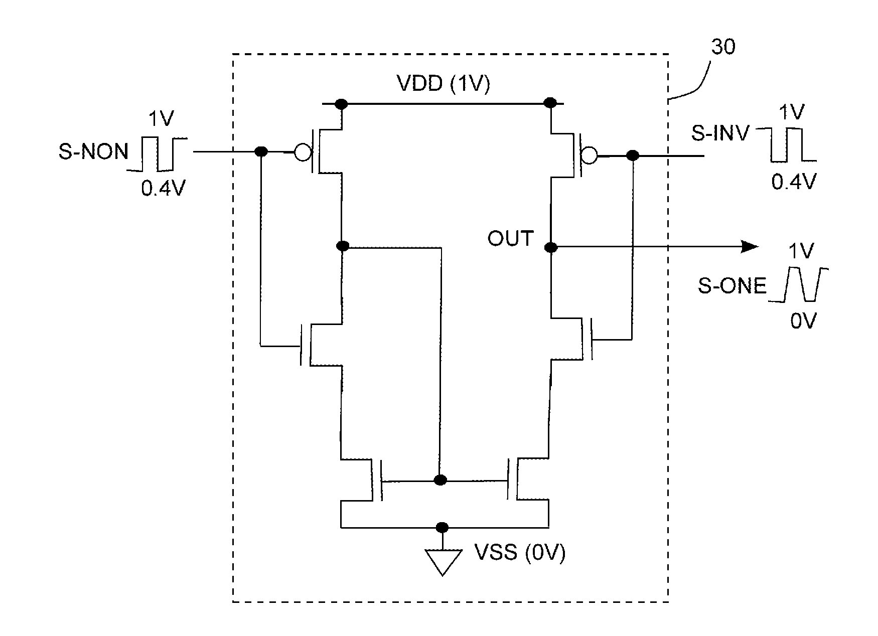
[0015]FIG. 2 shows a differential-to-single-end converter 20 according to an embodiment of the present invention. As shown in FIG. 2, the differential-to-single-end converter 20 includes two NMOS transistors N11 and N12, and four PMOS transistors P11, P12, P21 and P22. In one embodiment, element sizes of the NMOS transistors N11 and N12 are substantially the same; element sizes of the PMOS transistors P11 and P12 are substantially the same; element sizes of the PMOS transistors P21 and P22 are substantially the same.

[0016]The NMOS transistors N11 and N12 are a differential pair, whose gates are respectively driven by a non-inverted signal S-NON and an inverted signal S-INV of a differential signal. The NMOS transistor N11 and N12 have their sources jointly coupled to a power line VSS, and their drains not coupled to each other. Operation statuses of the NMOS transistors N11 and N12 are complementary. For example, the NMOS transistor N12 is turned off when the NMOS transistor N11 is ...


PUM


Abstract

A converter that converts a differential input signal to a single-end output signal is provided. The converter includes first, second, third and fourth transistors, and a pair of current sources. The first and second transistors are driven by the differential input signal, and have two conduction nodes coupled to each other and two conduction nodes not coupled to each other. The third and fourth transistors are driven by the differential input signal, and are connected in series with the first and second transistors. The pair of current sources, respectively connected in series with the third and fourth transistors, have a common control node coupled to the second conduction node of the first transistor. The second conduction node of the second transistor generates the single-end output signal.

Description

[0001]This application claims the benefit of Taiwan application Serial No. 102124538, filed Jul. 9, 2013, the subject matter of which is incorporated herein by reference.BACKGROUND OF THE INVENTION[0002]1. Field of the Invention[0003]The invention relates in general to a differential-to-single-end converter, and more particularly to a converter that converts a differential input signal to a single-end output signal.[0004]2. Description of the Related Art[0005]To withstand noises from power lines and a semiconductor substrate, internal signals of an integrated circuit may be processed by a differential mode. For example, a ring oscillator often generates clock signals by a differential mode to prevent common mode noises from affecting the frequency.[0006]However, a differential signal in the differential mode requires at least two signal transmission lines. Compared to one signal transmission line that a single-end signal requires, the design of the at least two signal transmission l...

Claims


Application Information

Patent Timeline
IPC IPC(8): H03F3/45
CPCH03F3/45179H03F2203/45091H03F2203/45364H03F2203/45394H03F2203/45646H03F2203/45674
Inventor CHEN, HSIN-KUANG
Owner XUESHAN TECH INC