Planar transmitter with a layered structure

a transducer and layered technology, applied in the field of interface technology with electronic components, can solve the problems of not using a magnetic core, transducer is not intrinsically safe, etc., and achieve the effect of safe galvanic isolation and space requiremen

Active Publication Date: 2015-01-22
PHOENIX CONTACT GMBH & CO KG
View PDF14 Cites 5 Cited by
  • Summary
  • Abstract
  • Description
  • Claims
  • Application Information

AI Technical Summary

Benefits of technology

[0015]According to an exemplary embodiment of the transducer according to the invention, an overall height of the transducer is four times a total insulation distance of a minimum insulation thickness T0.
[0016]According to the invention, a design of the required insulation for intrinsically safe operation is sized such that N−1 insulation thicknesses are now relocated to the horizontal extension of the transducer according to the invention, wherein N is the number of circuits used.
[0017]When relocating the circuits next to one another in the horizontal extension, it must be ensured that none of the circuits come closer than permissible to another potential group; this also applies in particular to the magnetic core.
[0018]According to an embodiment of the transducer according to the invention, it can be provided that an overall insulation thickness in the vertical extension of the transducer is 1×T0, wherein T0 is a minimum insulation distance. Therefore, one times T0 is required instead of N×T0 with conventional transducers, wherein N is the number of circuits which are safely galvanically isolated from one another.
[0019]According to an embodiment of the transducer according to the invention, with a required minimum insulation thickness T0 of an insulation layer of about 1 mm, the overall thickness of the transducer is not substantially greater than about 4 mm. Thicknesses of conductor tracks, insulation materials, ferrites, varnishes etc. are taken into account in the overall thickness of the transducer.
[0020]The geometry of the magnetic cores or core parts can also be optimized or minimized in such a way that the space requirement becomes minimal and the geometric shape of the cores or core parts becomes as simple as possible. This is in accord with a required cost optimization of electronic devices which contain intrinsically safe transducers.

Problems solved by technology

Here, however, the transducer is not an intrinsically safe transducer and neither is a magnetic core used.

Method used


Image

  • Planar transmitter with a layered structure
  • Planar transmitter with a layered structure
  • Planar transmitter with a layered structure

Examples


Embodiment Construction

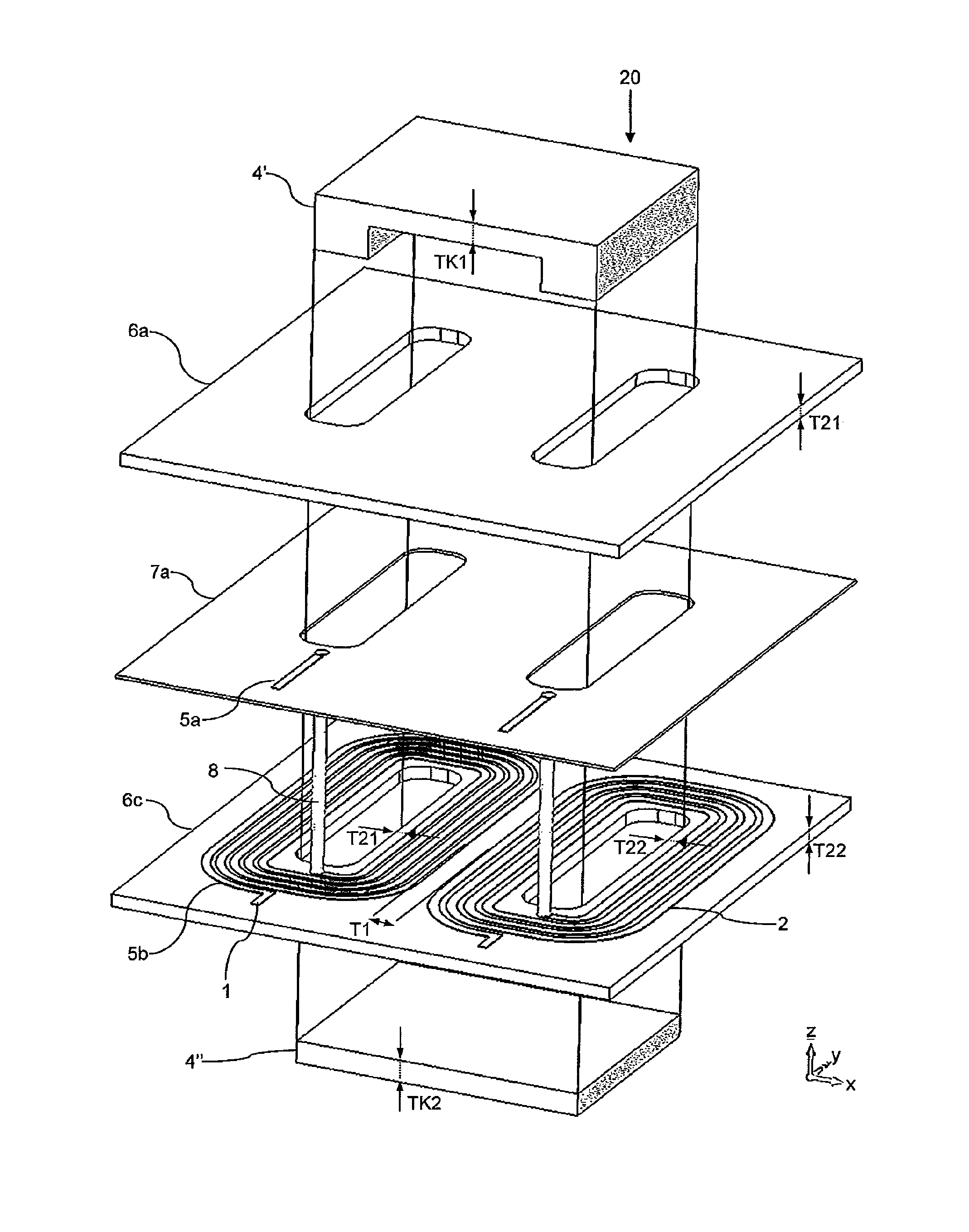
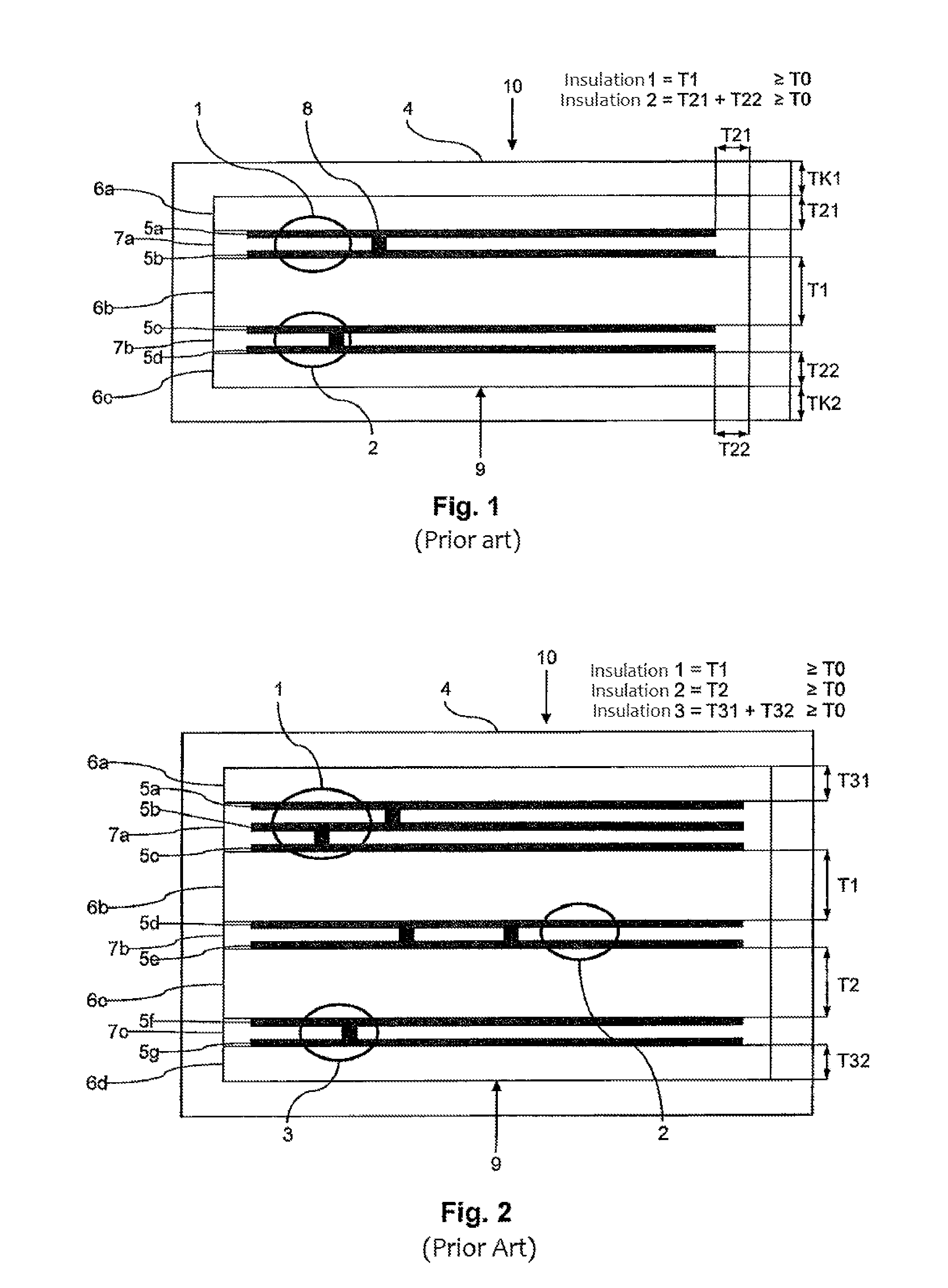
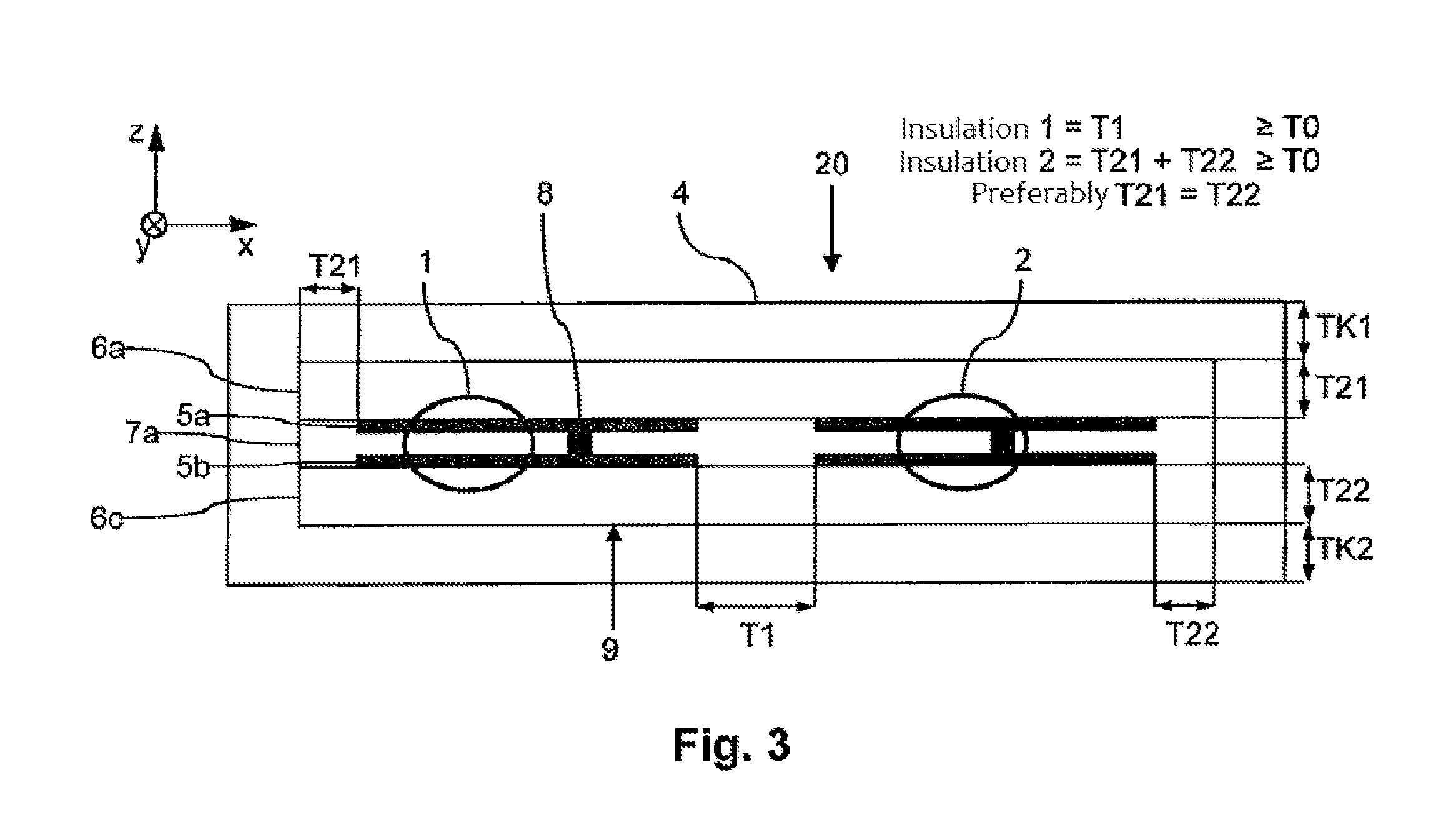
[0027]FIG. 1 shows a schematic diagram of a conventional transducer 10 with a first circuit 1 and a second circuit 2. The transducer 10 is designed as an intrinsically safe printed circuit board transducer, similar to the printed circuit board transducer as described, for example, in EP 0 715 322 A1. The transducer 10 has a layer structure with primary and a secondary side, which are formed by the two circuits 1, 2 respectively. The transducer or transformer is formed by an inductive coupling of the two circuits 1, 2 with, at the same time, galvanic isolation of the circuits 1, 2.

[0028]FIG. 1 shows a cross section through a printed circuit board 9 or printed circuit board arrangement 9, which is encompassed by a core 4, wherein the core 4 penetrates the printed circuit board 9 at a plurality of points. The penetration can be provided, for example, by milled holes in the printed circuit board 9. The printed circuit board 9 has a plurality of layers which are made up of layers of cond...


PUM

PropertyMeasurementUnit
thicknessaaaaaaaaaa
thicknessaaaaaaaaaa
insulation thickness T0aaaaaaaaaa

Abstract

A planar intrinsically safe transducer having a vertical extension and a horizontal extension having a layer structure with a plurality of circuits, wherein a first circuit and a second circuit are galvanically isolated from one another. Further, the transducer has a magnetic core 4, which at least partially encompasses the layer structure and acts at least on the first circuit and on the second circuit, wherein the first circuit and the second circuit lie in one plane and form a layer of the layer structure.

Description

FIELD OF THE INVENTION[0001]The present invention relates generally to the field of interface technology with electronic components which may be used for measurement, control and regulation tasks, in particular as isolating amplifiers. These isolating amplifiers provide galvanic isolation between a primary circuit and a secondary circuit and are suitable, for example, for intrinsically safe operation.[0002]The present invention relates to a transducer, in particular a planar transducer which is not susceptible to interference and which is suitable for intrinsically safe circuits, and is referred to in the following as a planar intrinsically safe transducer.BACKGROUND OF THE INVENTION[0003]Intrinsically safe transducers or transformers are used for the galvanic isolation of circuits in accordance with various standards, wherein energy as well as signals and / or data can be transmitted via the transducers.[0004]Minimum distances for the separation of the circuits and therefore also for...

Claims


Application Information

Patent Timeline
Patent Type & Authority Applications(United States)
IPC IPC(8): H01F27/28
CPCH01F2027/2819H01F27/2804H01F2027/2809H05K1/165H05K2201/086H01F2019/085
Inventor SCHOLZ, PETER-DOMINIK
Owner PHOENIX CONTACT GMBH & CO KG
Why Eureka
Try Eureka