Screw compressor with a sound dampening device that separates lubricant

a compressor and sound dampening technology, applied in the direction of intermeshing engagement type engines, rotary or oscillating piston engines, rotary piston engines, etc., can solve the problem of too much lubricant carrying along the compressed working medium of the screw compressor

Active Publication Date: 2013-08-06
BITZER KUEHLMASCHINENBAU GMBH
View PDF15 Cites 4 Cited by
  • Summary
  • Abstract
  • Description
  • Claims
  • Application Information

AI Technical Summary

Benefits of technology

[0008]The advantage of the solution according to the invention is to be seen in the fact that it offers the possibility of already carrying out a separation of lubricant in the sound damping device and, in this respect, of already removing, in the sound damping device, a considerable portion of the lubricant carried along with the working medium as a result of separation without the space required being increased and without additional space being required for this first separation of lubricant.
[0009]In this respect, it is particularly advantageous when lubricant is separated from the circulating flow of the working medium in the area of the flow guide, i.e. the lubricant carried radially outwards by centrifugal forces is separated at the flow guide.
[0011]A simple and advantageous design provides, however, for the flow guide to be designed as a wall which encloses the interior space and at which the separation of lubricant takes place.
[0020]Such a material pervious to lubricant serves the purpose of reducing the flow of working medium through the openings.
[0030]As a result, the inlet flow can be redirected by the flow guide into the circulating flow already described in a simple manner.

Problems solved by technology

The problem with these screw compressors is the fact that the compressed working medium leaving the screw compressor carries too much lubricant along with it, at least in some operating states.

Method used


Image

  • Screw compressor with a sound dampening device that separates lubricant
  • Screw compressor with a sound dampening device that separates lubricant
  • Screw compressor with a sound dampening device that separates lubricant

Examples


Embodiment Construction

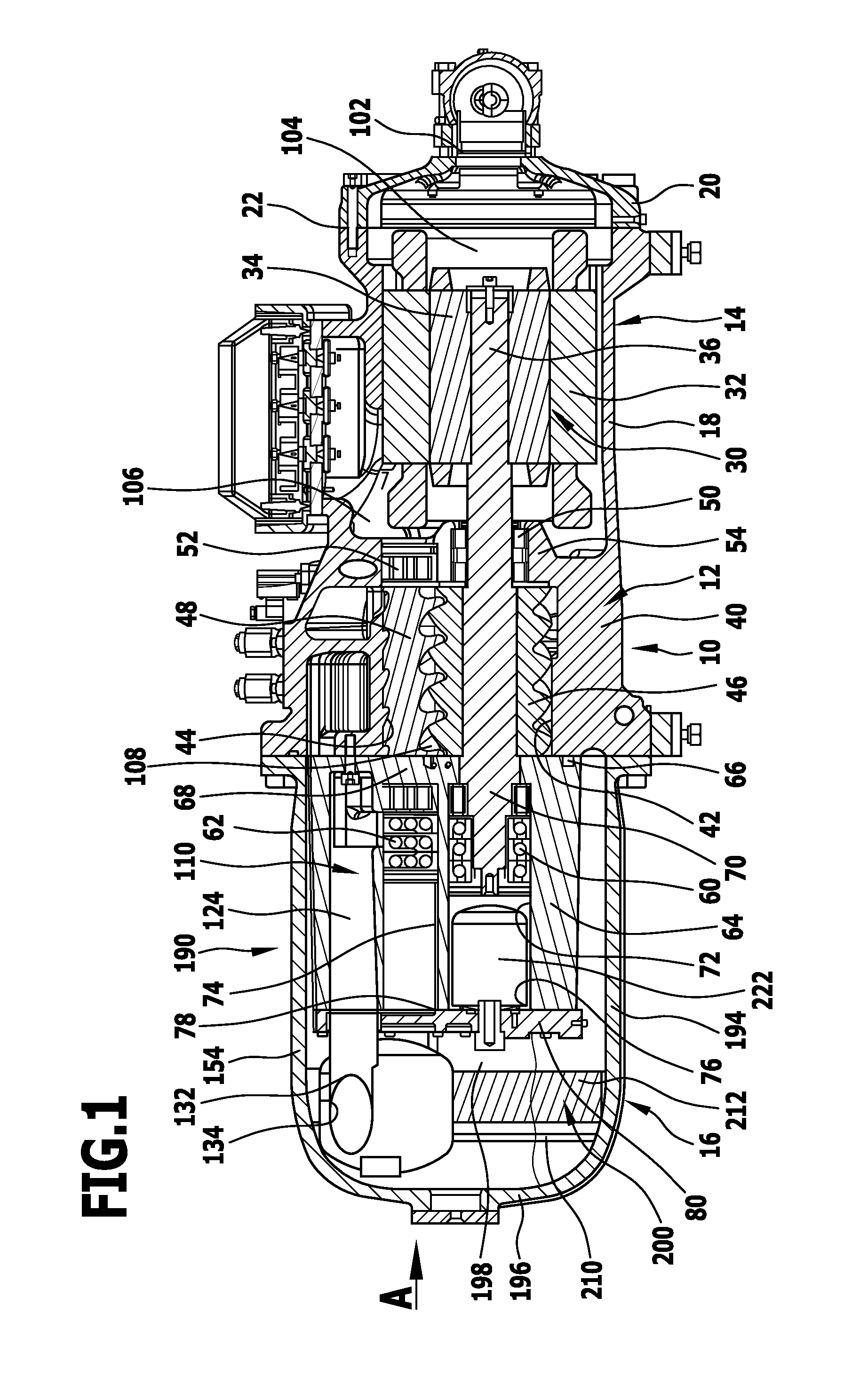
[0050]One embodiment of a screw compressor according to the invention, illustrated in FIG. 1, comprises an outer housing which is designated as a whole as 10 and consists of a central section 12, an end section 14 on the motor side and an end section 16 on the pressure side.

[0051]The end section 14 on the motor side is formed, for example, by a first housing sleeve 18 which is integrally formed on the central section 12 in one piece and is closed by a first housing cover 20 which is detachably connected to the first housing sleeve 18 via a flange connection 22.

[0052]A drive motor, which is designated as a whole as 30 and is designed, for example, as an electric motor, is arranged in the end section 14 on the motor side and has a stator 32 which is held in the first housing sleeve 18 and encloses a rotor 34, wherein the rotor 34 is seated on a drive shaft designated as a whole as 36.

[0053]A compressor screw housing which is designated as a whole as 40 is provided in the central secti...


PUM


Abstract

In order to improve a screw compressor comprising an outer housing, a compressor screw housing which is arranged in the outer housing and in which rotor bores for screw rotors are arranged, a drive arranged in the outer housing on one side of the compressor screw housing, a bearing housing arranged in the outer housing on a side of the compressor screw housing located opposite the drive and a sound damping device which is arranged within the outer housing and has compressed working medium flowing through it, in such a manner that the working medium leaving the screw compressor carries as little lubricant as possible along with it, it is suggested that the sound damping device guide the compressed working medium by means of a flow guide in an interior space as a circulating flow circulating around an axis and that lubricant be separated from the circulating flow of the working medium as a result of centrifugal forces.

Description

CROSS-REFERENCE TO RELATED PATENT APPLICATIONS[0001]This application is a continuation of international application number PCT / EP2009 / 058597 filed on Jul. 7, 2009.[0002]This patent application claims the benefit of International application No. PCT / EP2009 / 058597 of Jul. 7, 2009 and German application No. 10 2008 036 317.0 of Jul. 29, 2008, the teachings and disclosure of which are hereby incorporated in their entirety by reference thereto.BACKGROUND OF THE INVENTION[0003]The invention relates to a screw compressor comprising an outer housing, a compressor screw housing which is arranged in the outer housing and in which rotor bores for screw rotors are arranged, a drive arranged in the outer housing on one side of the compressor screw housing, a bearing housing arranged in the outer housing on a side of the compressor screw housing located opposite the drive and a sound damping device arranged within the outer housing and having the compressed working medium flowing through it.[0004...

Claims


Application Information

Patent Timeline
Patent Type & Authority Patents(United States)
IPC IPC(8): F01C1/18F01C1/24F04C2/18F04C2/24
CPCF04C18/16F04C29/026F04C18/165
Inventor FELLER, KLAUSLOERCH, RONI
Owner BITZER KUEHLMASCHINENBAU GMBH
Why Eureka
Try Eureka