Humidification control method for fuel cell and fuel cell system

Active Publication Date: 2015-01-22
HONDA MOTOR CO LTD
View PDF5 Cites 15 Cited by
  • Summary
  • Abstract
  • Description
  • Claims
  • Application Information

AI Technical Summary

Benefits of technology

[0020]In the present invention, measurement of impedance is easily performed using alternating current of a l

Problems solved by technology

For this purpose, since structure and control to change the frequency of the alternating current is required, the fuel cell system tends to be complicated and a long period of time is required for measurement of impedance disadvant

Method used


Image

  • Humidification control method for fuel cell and fuel cell system
  • Humidification control method for fuel cell and fuel cell system
  • Humidification control method for fuel cell and fuel cell system

Examples


Example

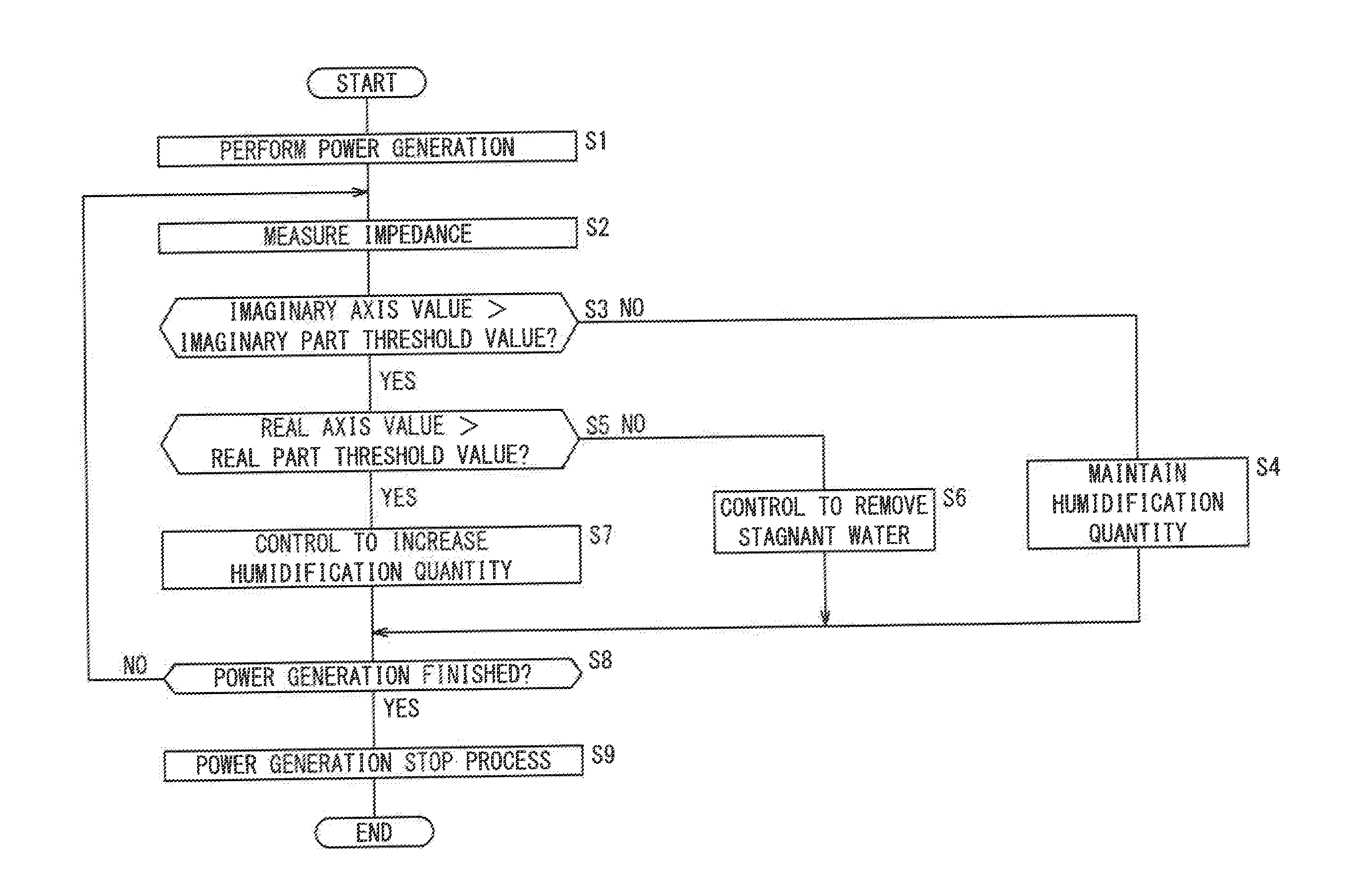
[0030]Hereinafter, a preferred embodiment of a humidification control method for a fuel cell according to the present invention will be described in relation to a fuel cell system, and the embodiment will be described in details with reference to the drawings.

[0031]During power generation of a fuel cell, a fuel cell system according to an embodiment of the present invention measures impedance of the fuel cell, and implements humidification control for the fuel cell. For example, this fuel cell system is mounted in an automobile as an in-vehicle system for supplying electrical energy to a power source such as a motor during traveling of the automobile. It should be noted that the fuel cell system is not limited for use in the in-vehicle application. The fuel cell system may be used in various applications such as a stationary application.

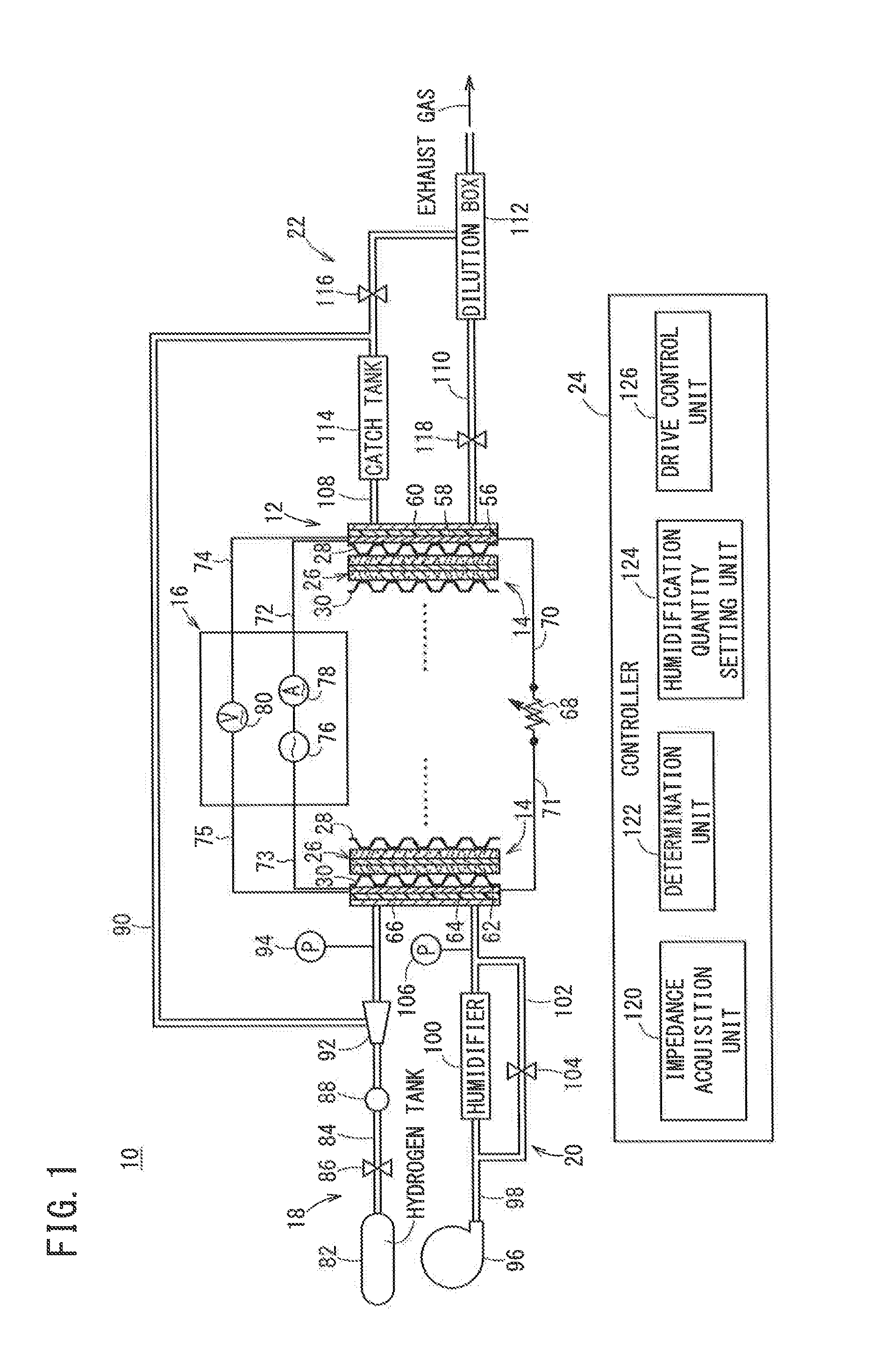
[0032]As shown in FIG. 1, a fuel cell system 10 includes a fuel cell stack 12 formed by stacking a plurality of fuel cells 14, and an impedance meas...


PUM


Abstract

A method of controlling humidification of a fuel cell includes the steps of measuring impedance of the fuel cell, and adjusting humidification quantity of the fuel cell based on an imaginary axis value Xi and a real axis value Xr on a complex number plane of the measured impedance after the measurement step. In the measurement step, impedance is measured based on supply of alternating current having one frequency of 10 Hz or less during power generation of the fuel cell.

Description

CROSS-REFERENCE TO RELATED APPLICATIONS[0001]This application is based upon and claims the benefit of priority from Japanese Patent Applications No. 2013-151594 filed on Jul. 22, 2013 and No. 2014-131578 filed on Jun. 26, 2014, the contents all of which are incorporated herein by reference.BACKGROUND OF THE INVENTION[0002]1. Field of the Invention[0003]The present invention relates to a humidification control method for a fuel cell and a fuel cell system. The fuel cell is formed by stacking an electrolyte electrode assembly and a separator. The electrolyte electrode assembly includes a cathode, an anode, and an electrolyte interposed between the cathode and the anode.[0004]2. Description of the Related Art[0005]For example, a fuel cell includes a membrane electrode assembly (MEA) and separators sandwiching the MEA. The membrane electrode assembly includes a cathode, an anode, and an electrolyte membrane (or an electrolyte) interposed between the cathode and the anode. The electrolyt...

Claims


Application Information

Patent Timeline
IPC IPC(8): H01M8/04
CPCH01M8/04492H01M2008/1095H01M8/04828H01M8/04835H01M8/04649Y02E60/50
Inventor HIBINO, KIYOHIDEIWASAWA, CHIKARA
Owner HONDA MOTOR CO LTD
Why Eureka
Try Eureka