Engine speed control apparatus

a control apparatus and engine technology, applied in the direction of electric control, speed sensing governors, combustion engines, etc., can solve the problems of control system running into a state in which control cannot be sufficiently carried out, parts come to a cost problem in the general purpose engine in which a low cost is demanded, etc., to achieve low cost, easy to ensure reliability, and simple apparatus structure

Inactive Publication Date: 2009-05-14
NIKKI CO LTD
View PDF2 Cites 5 Cited by
  • Summary
  • Abstract
  • Description
  • Claims
  • Application Information

AI Technical Summary

Benefits of technology

[0015]With regard to the throttle valve opening end closing means drivingly operated by the electronic control means controlling the engine speed, in the present invention, since it is possible to control both the motions in the opening direction and the closing direction of the throttle valve by drivingly operating the motor only in one direction by utilizing the energizing force of the return spring, the structure of the apparatus becomes simple without necessity of a lot of drive circuits for driving the motor such as the conventional one, and it is possible to achieve the low cost while easily securing a reliability.
[0016]Further, if the throttle valve opening and closing means is structured such as to carry out an angle position control of the throttle valve closing motion by the return spring as well as carrying out the opening motion of the throttle valve on the basis of a turning force in a fixed direction by the motor, it is possible to rapidly and suitably control on the basis of a comparatively simple structure and a simple processing procedure.
[0017]Further, in the engine speed control apparatus mentioned above, if the electronic control means is structured such as to execute the engine speed control in accordance with a predetermined robust sliding mode control in place of the PID control, it is easy to secure a stability and an accuracy of the control even in a servo system engine speed control in which a high robustness is demanded.
[0018]Further, in the engine speed control apparatus using the robust sliding mode control, if the feedback control is carried out by using only the engine speed data detected by the electronic control means, and the predetermined engine speed is maintained without using the throttle angle sensor, it is possible to omit the throttle angle sensor and a lower cost can be achieved.
[0019]In accordance with the present invention in which both the open and close motions of the throttle valve are controlled by driving controlling the motor only in one direction by using the return spring, it is possible to achieve a good rotating speed control in the general purpose engine, without increasing the cost and lowering the reliability of the apparatus.

Problems solved by technology

For example, in the case of a direct-current motor, since four power semiconductors and a circuit switching the normal rotation and the reverse rotation are normally necessary as the drive circuit, the apparatus becomes complicated.
Further, since a throttle angle sensor is necessary for controlling the throttle angle in addition to the sensor for detecting the engine speed, a lot of these parts come to a problem on cost in the general purpose engine in which a low cost is demanded.
On the other hand, in the rotating speed control of the general purpose engine by the electronic governor mentioned above, the electronic control apparatus constructing a part of the electronic governor generally PID controls a command value output to a step motor or the like corresponding to an actuator, however, in the case that a characteristic of a controlled object is changed in the control system mentioned above in which a lot of nonlinear elements exist, the control system tends to run into a state in which the control can not be sufficiently carried out.
However, the sensors and the drive circuit for the forward and reverse rotations mentioned above are necessary even in this technique, and the problems in the view of the cost and the reliability of the apparatus are not solved.
Accordingly, this technique has not yet led to a wide spread in the general purpose engine field.

Method used


Image

  • Engine speed control apparatus
  • Engine speed control apparatus
  • Engine speed control apparatus

Examples


Embodiment Construction

[0023]A description will be given below of a best mode for carrying out the present invention with reference to the accompanying drawings.

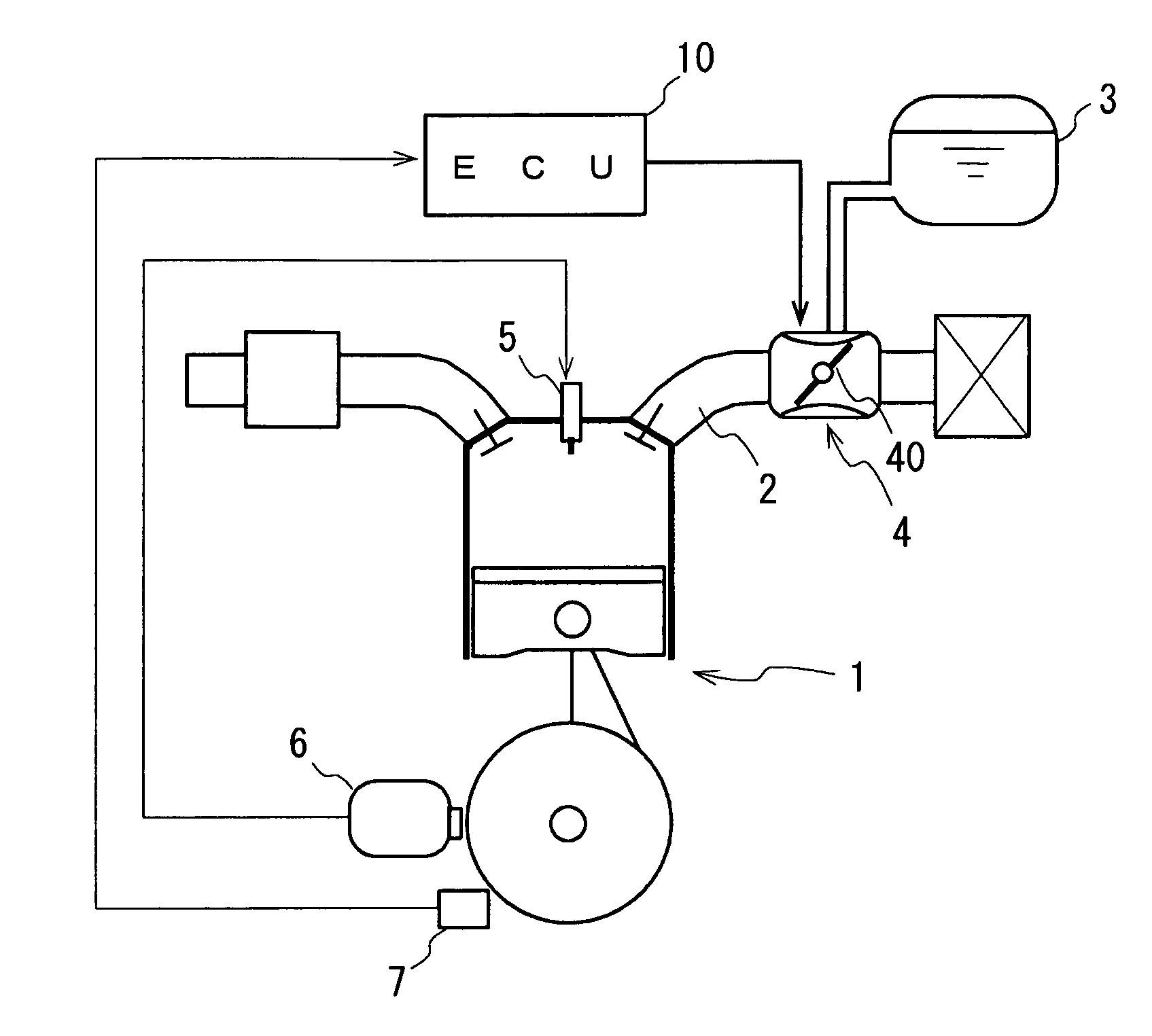
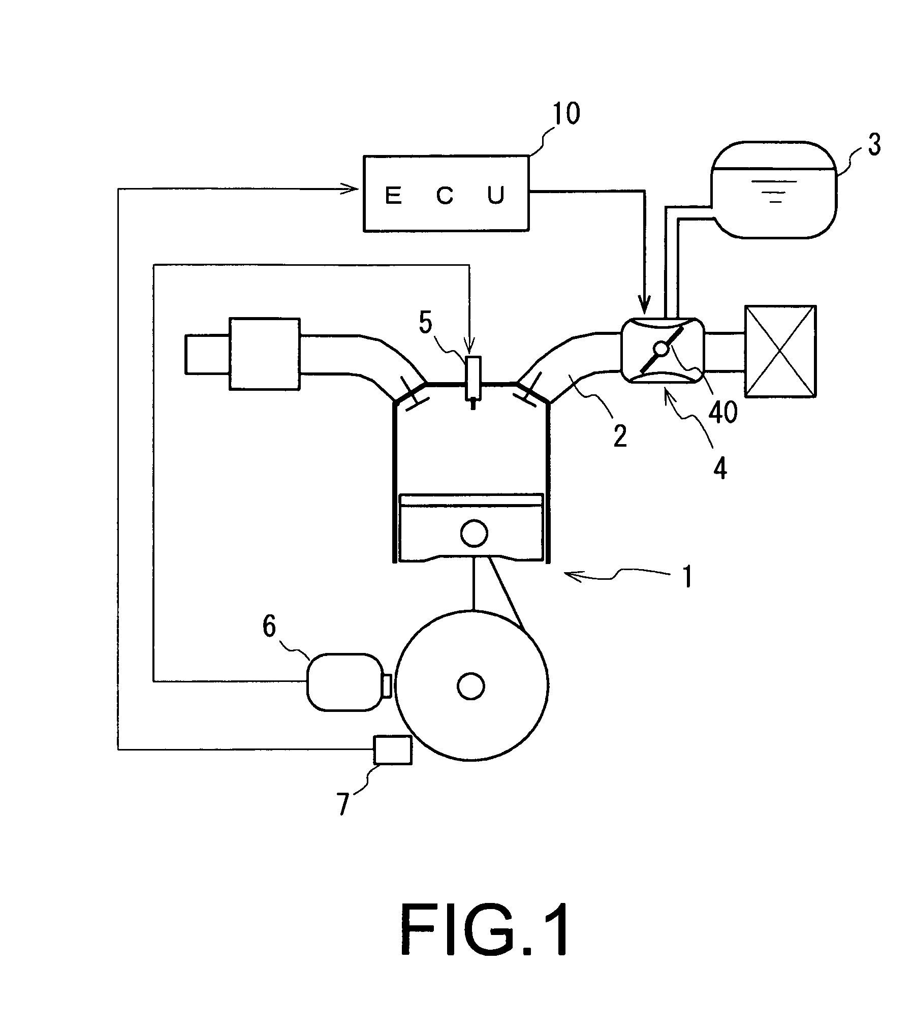
[0024]FIG. 1 shows an engine system in which an engine speed control apparatus in accordance with the present embodiment is arranged, in which an engine 1 is assumed by a general purpose engine, however, an electronic governor apparatus 4 doubling as a carburetor while being provided with a throttle valve 40 and serving as a throttle valve opening and closing means is arranged in the middle of an intake passage 2. Further, a fuel supply piping from a fuel tank 3 is connected to a carburetor part of the electronic governor apparatus 4.

[0025]On the other hand, an ignition apparatus 6 is arranged in an outer peripheral side of a flywheel of the engine 1 so as to output an ignition signal to an ignition plug 5. A crank angle sensor 7 is arranged near the ignition apparatus 6 so as to output a detection signal to an electronic control unit 10.

[0026]Acc...


PUM


Abstract

The invention achieves a good engine speed control without increasing a cost and a lowering a reliability of an apparatus in a general purpose engine. In a rotating speed control apparatus of an engine in which an electronic control unit (10) controls an engine speed by operating so as to open and close a throttle valve (40) by an electronic governor apparatus (4) on the basis of an engine speed detected by a crank angle sensor (7) corresponding to an engine speed detecting means and regulating an intake air amount, the opening and closing operation of the throttle valve (40) in the electronic governor apparatus (4) is carried out by a rotating force of a motor rotationally driven only in one direction and an elastic repulsive force of a return spring energizing in a reverse direction.

Description

BACKGROUND OF THE INVENTION[0001]1. Field of the Invention[0002]The present invention relates to an engine speed control apparatus of a general purpose engine.[0003]2. Description of Related Art[0004]Conventionally, as described in Japanese Unexamined Patent Publication No. 4-116256, there has been in widespread an electronic governor in which an engine speed is maintained at a predetermined speed by controlling a throttle valve opening degree by an electronic control means via a motor-driven actuator.[0005]An engine speed control by the electronic governor mentioned above is carried out by feedback processing a detected signal of the engine speed (the rotating speed) and driving a motor controlling an angle of a throttle valve, however, since the motor controls a throttle angle position on the basis of a feedback signal, it is necessary to carry out a forward rotation and a reverse rotation in the driving operation of the motor.[0006]Accordingly, both driving circuits for the forwa...

Claims


Application Information

Patent Timeline
Patent Type & Authority Applications(United States)
IPC IPC(8): F02D11/10
CPCF02D11/10F02D31/002Y02T10/42F02D41/1403F02D2041/1409F02D41/0002Y02T10/40
Inventor SAWUT, UMERUJANYAMAGUCHI, SHINYA
Owner NIKKI CO LTD
Why Eureka
Try Eureka