Heat exchanger cleaning tool with three axis control

a technology of heat exchanger and cleaning tool, which is applied in the direction of cleaning heat-transfer devices, cleaning processes and apparatuses, and cleaning using liquids, etc., can solve the problems of reducing the heat transfer between the heat exchanger tubes and fouling the tubes with impurities in water

Active Publication Date: 2015-02-05
CLEAN HARBORS IND SERVICES INC
View PDF3 Cites 48 Cited by
  • Summary
  • Abstract
  • Description
  • Claims
  • Application Information

AI Technical Summary

Benefits of technology

[0007]The present invention further provides a heat exchanger cleaning apparatus that includes an articulated arm assembly having a lance attached thereto. The articulated arm assembly has a base fixedly attached to a heat exchanger having a tubing face, a primary arm pivotally attached to the base, and a secondary arm pivotally attached to the primary arm, so that the primary and second

Problems solved by technology

The result of this circulation is that impurities in the water foul the tubes over time.
As fouling builds up, th

Method used


Image

  • Heat exchanger cleaning tool with three axis control
  • Heat exchanger cleaning tool with three axis control
  • Heat exchanger cleaning tool with three axis control

Examples


Embodiment Construction

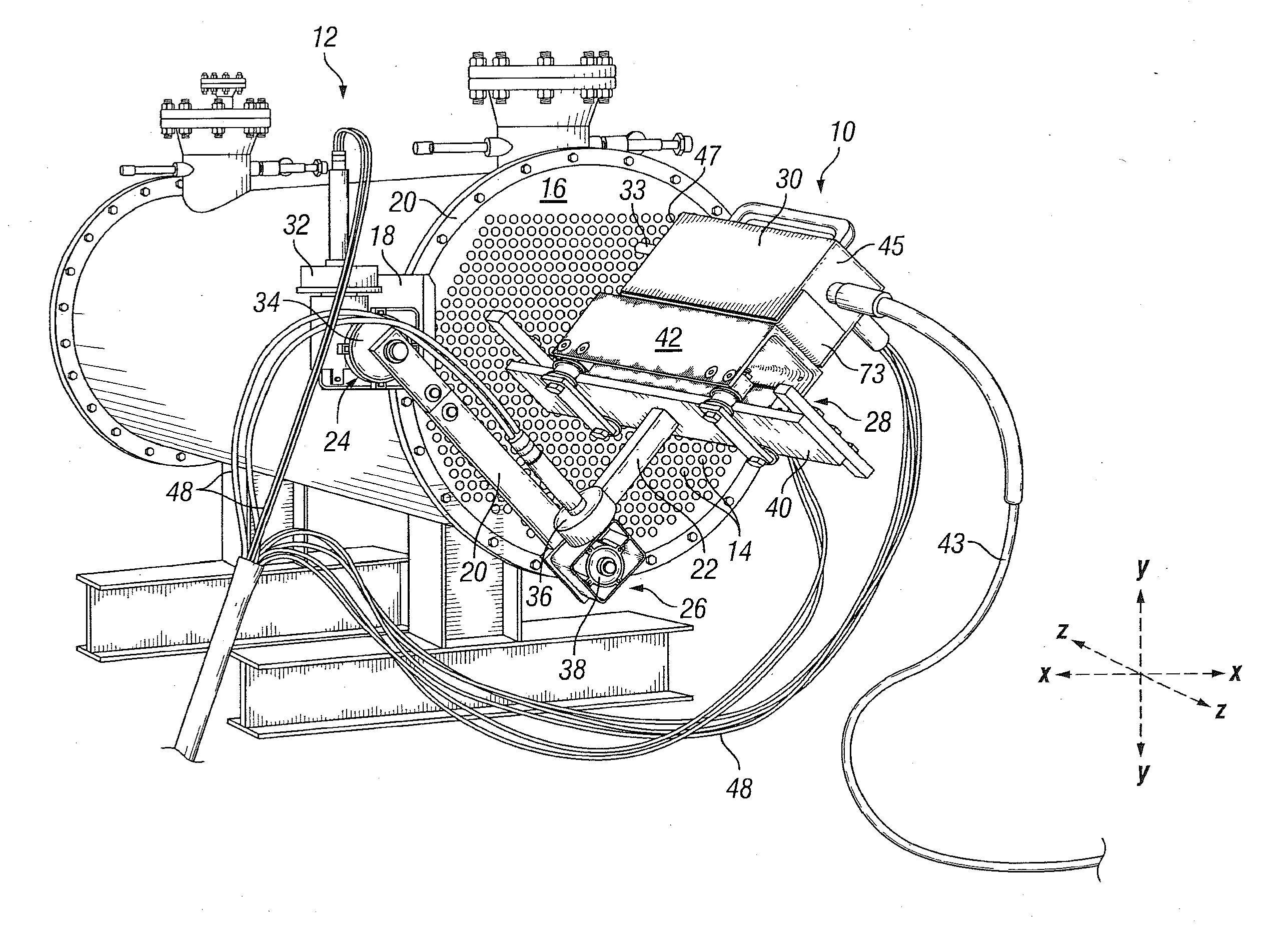
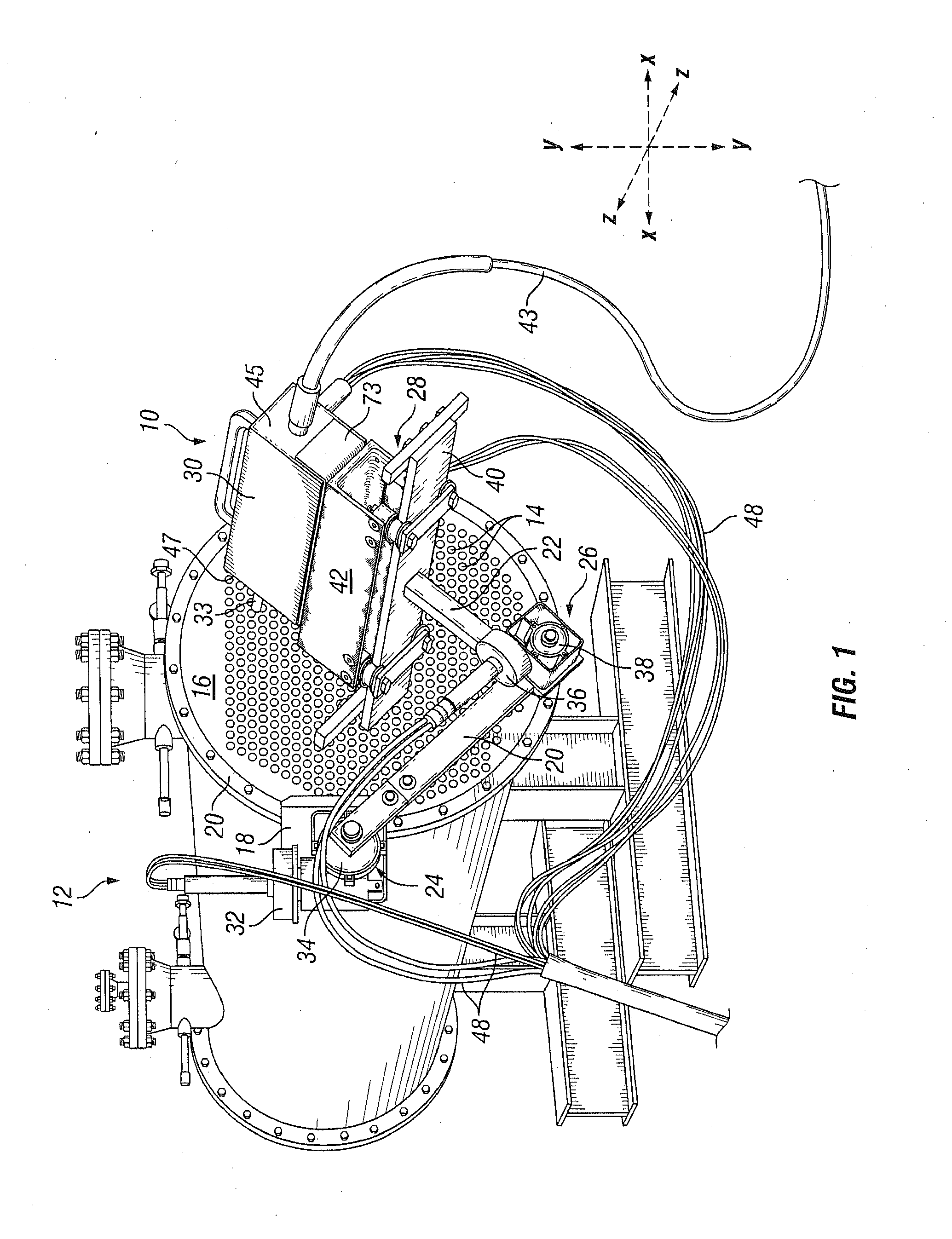
[0015]In FIG. 1, there is depicted a heat exchanger tube cleaning tool 10 according to the present invention for cleaning a conventional heat exchanger 12. Typically, a heat exchanger 12 includes a plurality of tubes 14 that terminate at a tube face 16. The tube face 16 is typically planar, and oriented vertically when the heat exchanger 12 is positioned as intended on flat ground. Each of the tubes 14 is open at the tube face 16, and extends longitudinally through the heat exchanger 12. Over time, the tubes 14 may become dirty, or may accumulate contaminates that limit the flow of fluid through the tubes 14. Accordingly, it advantageous to clean the tubes periodically to enable efficient operation of the heat exchanger 12.

[0016]Cleaning of the heat exchanger tubes 14 may be accomplished using the heat exchanger tube cleaning tool 10 shown in FIG. 1. The heat exchanger tube cleaning tool 10 includes a base 18 configured for attachment to a flange 20 of the heat exchanger 12 adjacent...


PUM


Abstract

A tool for cleaning a heat exchanger that includes a lance, and an articulated arm fixedly attached to the heat exchanger at a first end, and associated with the lance at a second end. The articulated arm has at least two joints so that the articulated arm can move the lance along two axes in a plane substantially parallel to the tube face of the heat exchanger. The tool further includes a lance transport mechanism attached to the second end of the articulated arm that moves toward and away from the tube face of the heat exchanger in a direction substantially perpendicular to the tube face, the lance transport mechanism attached to the lance so that the lance moves toward and away from the tube face along with the lance transport mechanism.

Description

BACKGROUND OF THE INVENTION[0001]1. Field of the Invention[0002]The present invention relates to a tool for cleaning tubes in heat exchangers, and in particular to a tool that moves a tube cleaning lance along three axes into alignment with tubes to be cleaned, and to directs or guides the lance into the tubes to be cleaned.[0003]2. Description of the Related Art[0004]In a number of industrial facilities, surface condensers, or heat exchangers, are used to convert steam to liquid water. These heat exchangers require the circulation of large quantities of water through tubes within the heat exchangers. The result of this circulation is that impurities in the water foul the tubes over time.[0005]Depending on the extent of the fouling, the impact on the efficiency and performance of the heat exchangers can be dramatic. As fouling builds up, the contaminates insulate the tubes, thereby diminishing the heat transfer between tubes within the heat exchanger. In order to control fouling and...

Claims


Application Information

Patent Timeline
IPC IPC(8): F28G1/16F28G15/04B08B9/032
CPCF28G1/163F28G15/04B08B9/0321B08B9/04B08B9/043B08B9/0433F28G15/02
Inventor BRUMFIELD, MICHAEL KENNETH
Owner CLEAN HARBORS IND SERVICES INC
Why Eureka
Try Eureka