Tooth impact guard

a technology of impact guards and teeth, applied in the field of mouth and tooth protection devices, can solve the problems of affecting the ability to speak clearly, affecting the effect of mouth guards, and affecting the ability to protect teeth,

Inactive Publication Date: 2015-03-05
POWERS MICHAEL
View PDF5 Cites 7 Cited by
  • Summary
  • Abstract
  • Description
  • Claims
  • Application Information

AI Technical Summary

Benefits of technology

The patent describes how a new type of sports mouthpiece called a guard can be made. This involves making an impression of the player's teeth, cast them onto that impression with plastic, and make a final shape out of it. Then, this finished shape is used to make a custom-fitted bracket for the player. The resulting guide helps protect the player's dental health during training or games.

Problems solved by technology

The technical problem addressed in this patent is how to design a protective device that can be fitted snugly on the teeth without interfering with speaking or swallowing, and also provides strong impact resistance to prevent dental injuries during sport activities. Current mouthguards tend to obstruct the tongue and make it difficult to communicate effectively, leading to poor performance and potential safety issues. This new technology seeks to overcome these limitations by developing an improved tooth-impact guard designed specifically to address these concerns.

Method used


Image

  • Tooth impact guard
  • Tooth impact guard
  • Tooth impact guard

Examples


Embodiment Construction

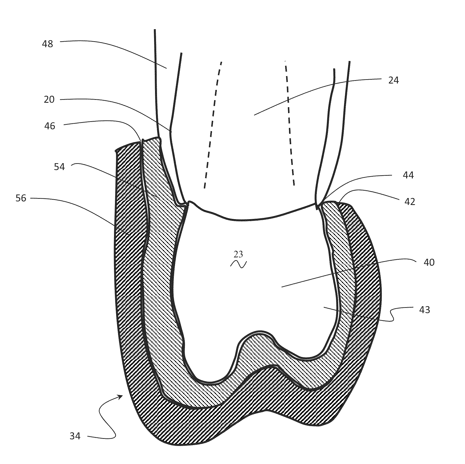
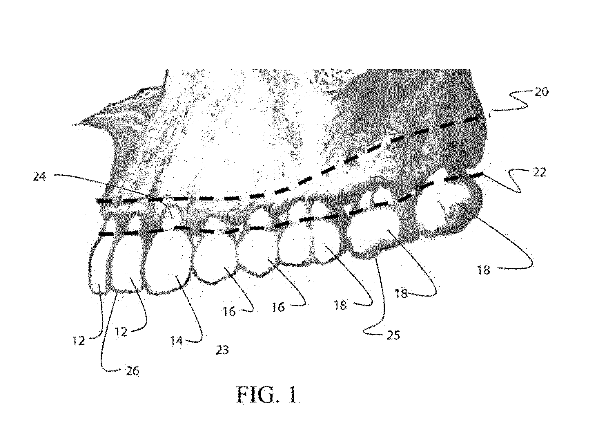
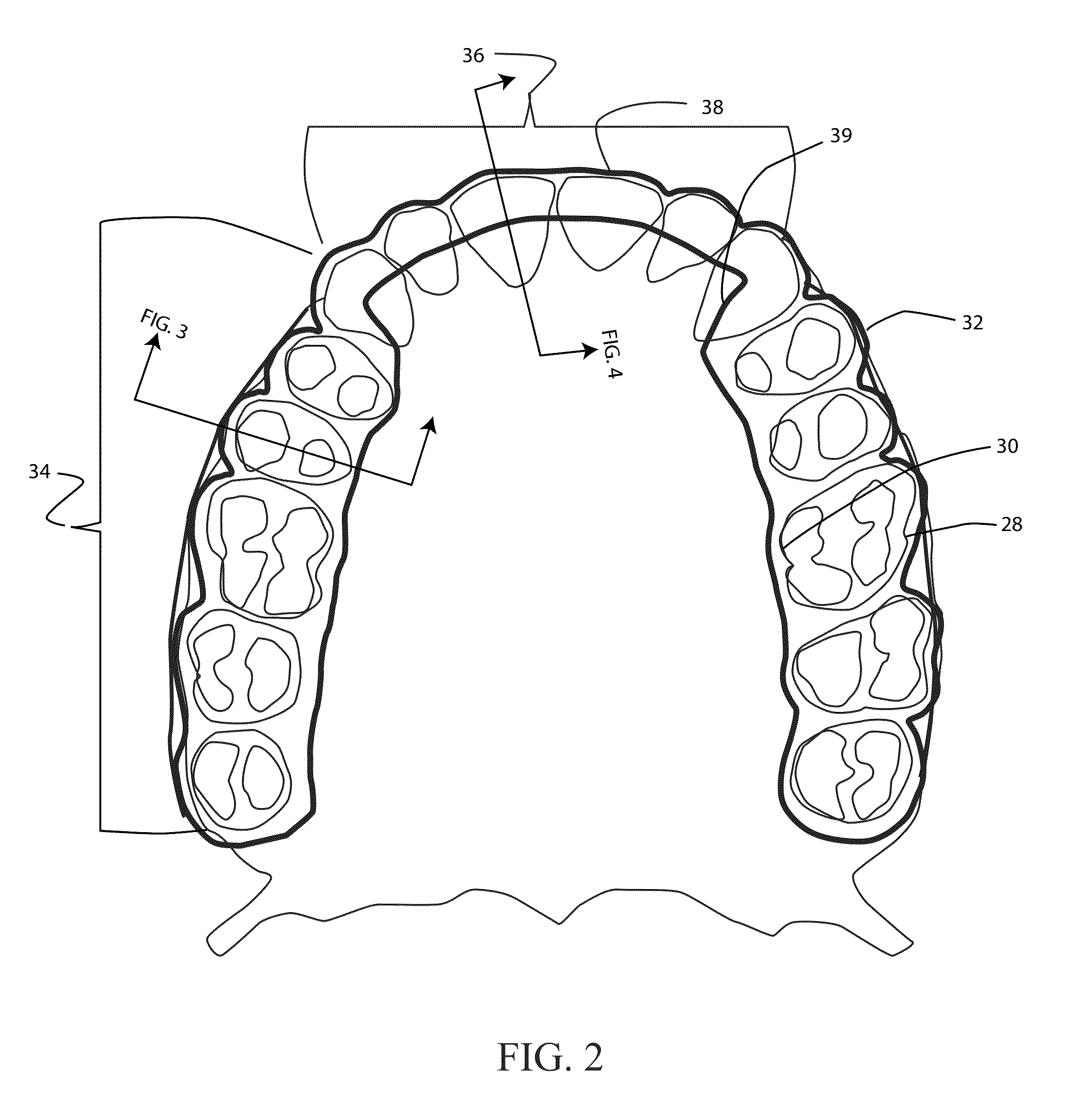
[0018]Embodiments disclosed herein provide a tooth impact guard having an inner layer formed of a rigid or hard acrylic (referred to herein as a rigid acrylic) and an outer layer formed of a flexible, compressible, energy absorbing acrylic (referred to herein as a soft acrylic). The added strength and retention provided by the inner rigid acrylic layer allows removal of all material from the roof of the mouth and from behind the front teeth. The removal of this material means there is no deleterious effect on speech, breathing or swallowing, and these are the major complaints associated with prior art mouthguards. The resulting guard has an outer upper profile or labial margin which extends proximate to the alveolar ridge adjacent all teeth and an inner upper profile or lingual margin that extends to the cemento enamel junction adjacent the posterior teeth but is relieved substantially to but overlapping the lingual incisal edge adjacent the anterior teeth. The desired high impact p...


PUM


Abstract

A tooth impact protection guard incorporates a posterior portion with a labial margin substantially at a contour of an alveolar ridge. The posterior portion extends over an occlusal surface of each posterior tooth and covers the lingual cusps to a posterior lingual margin at the cemento-enamel junction. An anterior portion has a contiguous labial margin with the posterior portion at a contour of the attached alveolar ridge. The anterior portion terminates in an anterior lingual margin substantially adjacent an incisal edge of each anterior tooth with an overlap of between 2 and 5 mm.

Description


Claims


Application Information

Patent Timeline
Owner POWERS MICHAEL
Why Eureka
Try Eureka