Encoding method and decoding method, and device using same
a technology of encoding and decoding method, applied in the field of video encoding and decoding technology, can solve the problems of the difficulty in effectively handling a luma signal and a chroma signal separately, and achieve the effect of improving the encoding/decoding efficiency, and reducing the bandwidth of the channel
- Summary
- Abstract
- Description
- Claims
- Application Information
AI Technical Summary
Benefits of technology
Problems solved by technology
Method used
Image
Examples
embodiment 1
[0154]A method and apparatus for deriving a scanning direction for a chroma signal based on an intra-prediction direction mode of a luma signal
[0155]FIG. 12 is a flowchart illustrating an example of a method of deriving a scanning direction for a chroma signal according to the present embodiment.
[0156]In the example of FIG. 12, the derivation of a scanning direction for a chroma signal can be determined by an intra-prediction direction mode of a luma signal. In other words, a scanning direction for a luma signal can be applied to a chroma signal without change. Accordingly, there is an advantage in that complexity is reduced because it is not necessary to derive calculation for deriving a scanning direction for a chroma signal.
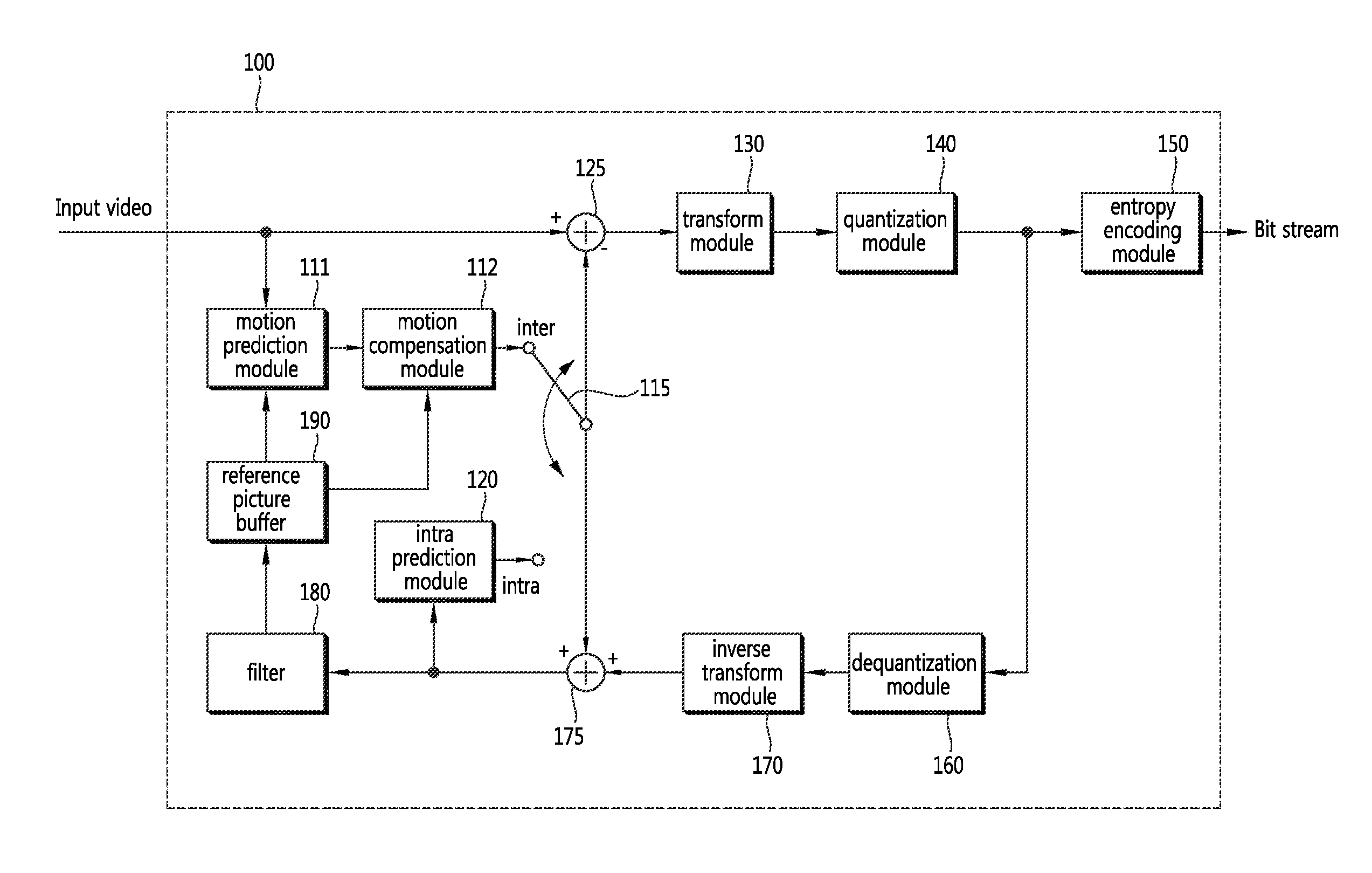
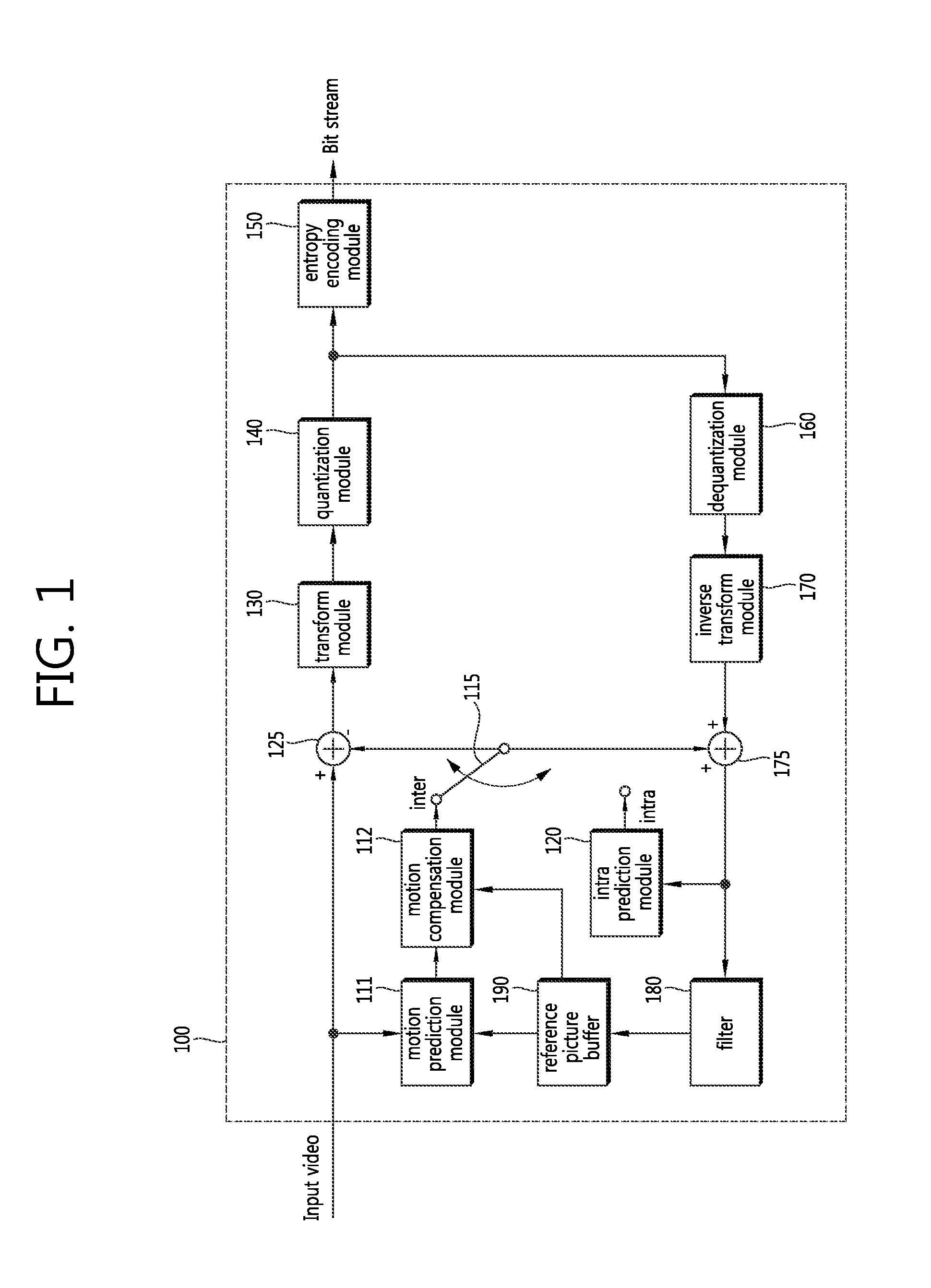
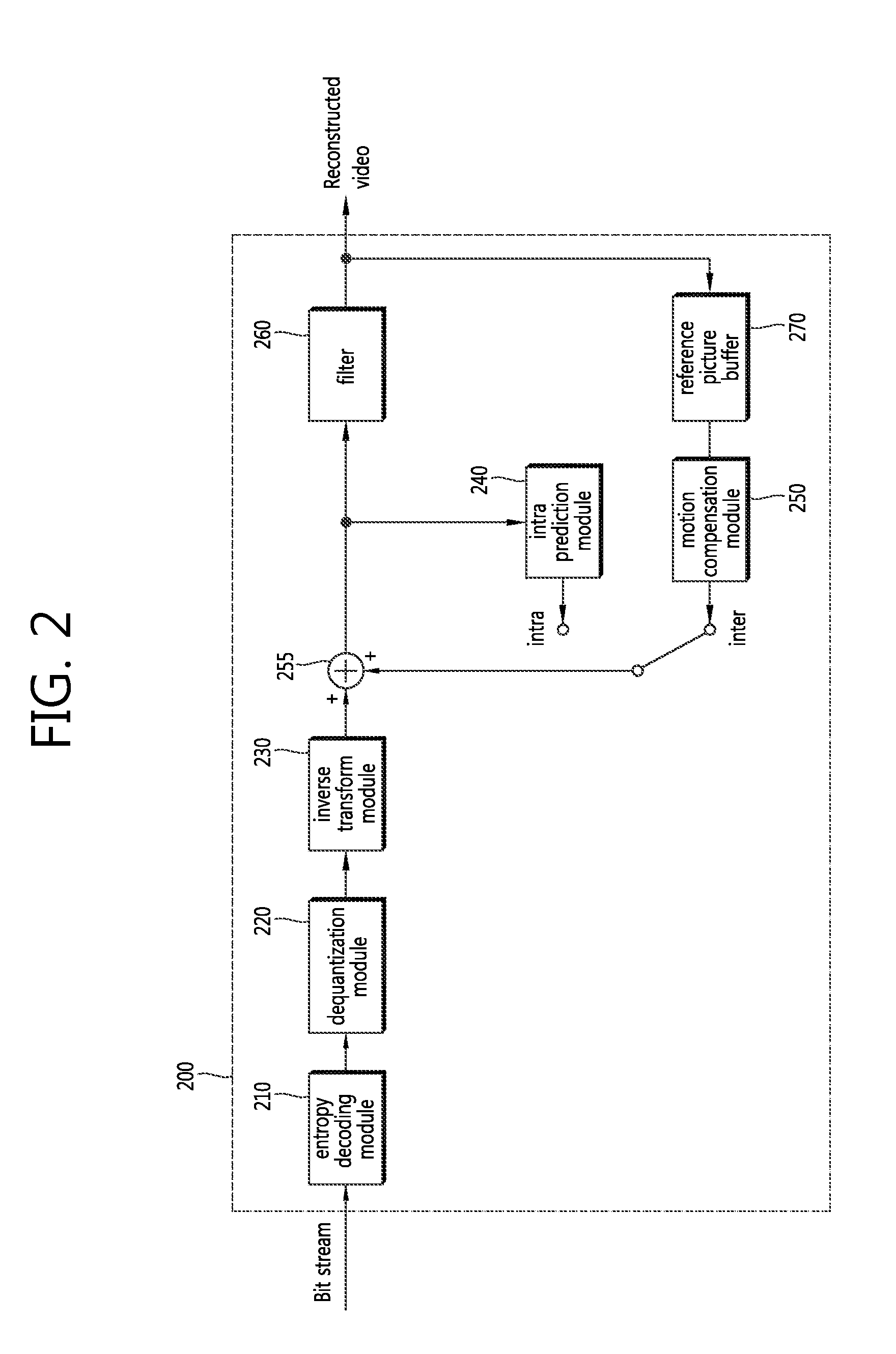
[0157]The operation of FIG. 12 can be performed in the encoding apparatus of FIG. 1 and the decoding apparatus of FIG. 2.
[0158]Referring to FIG. 12, whether or not the luma component of a current block has been subjected to intra-prediction is determined at st...
embodiment 2-1
[0186]A method and apparatus for applying a scanning direction for a luma signal to a chroma signal without change when an intra-prediction direction mode for the chroma signal is ‘Intra_FromLuma’
[0187]FIG. 14 is a flowchart illustrating an embodiment of a method of deriving a scanning direction for a chroma signal according to the present embodiment.
[0188]Referring to FIG. 14, whether or not an intra-prediction direction mode for the chroma signal of a current block is an intra-prediction mode is determined at step S1410. If, as a result of the determination, it is determined that an intra-prediction mode has not been applied to the current block, up-right diagonal scanning is performed on the current block at step S1480.
[0189]If, as a result of the determination, it is determined that the current block has been subjected to intra-prediction, whether or not the intra-prediction mode for the chroma signal of the current block is Intra_FromLuma is determined at step S1420. If, as a r...
embodiment 2-2
[0194]A method and apparatus for applying a scanning direction for a luma signal to a chroma signal without change when the intra-prediction direction of the chroma signal is the same as the intra-prediction direction of the luma signal or an intra-prediction mode for the chroma signal is Intra_FromLuma
[0195]FIG. 15 is a flowchart illustrating another embodiment of a method of deriving a scanning direction for a chroma signal according to the present embodiment.
[0196]From FIG. 15, it can be seen that a DM method (i.e., a method of using an intra-prediction direction mode for a luma signal as an intra-prediction direction mode for a chroma signal or it means that the intra-prediction direction of the chroma signal becomes equal to the intra-prediction direction of the luma signal) and the LM (Intra_FromLuma) method are unified into one.
[0197]First, whether or not a current block has been subjected to intra-prediction is determined at step S1505. If, as a result of the determination, ...
PUM
 Abstract
Description
Claims
Application Information
 - R&D
- Intellectual Property
- Life Sciences
- Materials
- Tech Scout
- Unparalleled Data Quality
- Higher Quality Content
- 60% Fewer Hallucinations
Browse by: Latest US Patents, China's latest patents, Technical Efficacy Thesaurus, Application Domain, Technology Topic, Popular Technical Reports.
© 2025 PatSnap. All rights reserved.Legal|Privacy policy|Modern Slavery Act Transparency Statement|Sitemap|About US| Contact US: help@patsnap.com


