Image encoding/decoding method and device therefor
A technology of image and coded image, applied in image communication, digital video signal modification, electrical components, etc., can solve the problems of memory storage, memory access rate and processing capacity growth, and achieve the effect of reducing the amount of data
- Summary
- Abstract
- Description
- Claims
- Application Information
AI Technical Summary
Problems solved by technology
Method used
Image
Examples
Embodiment 1
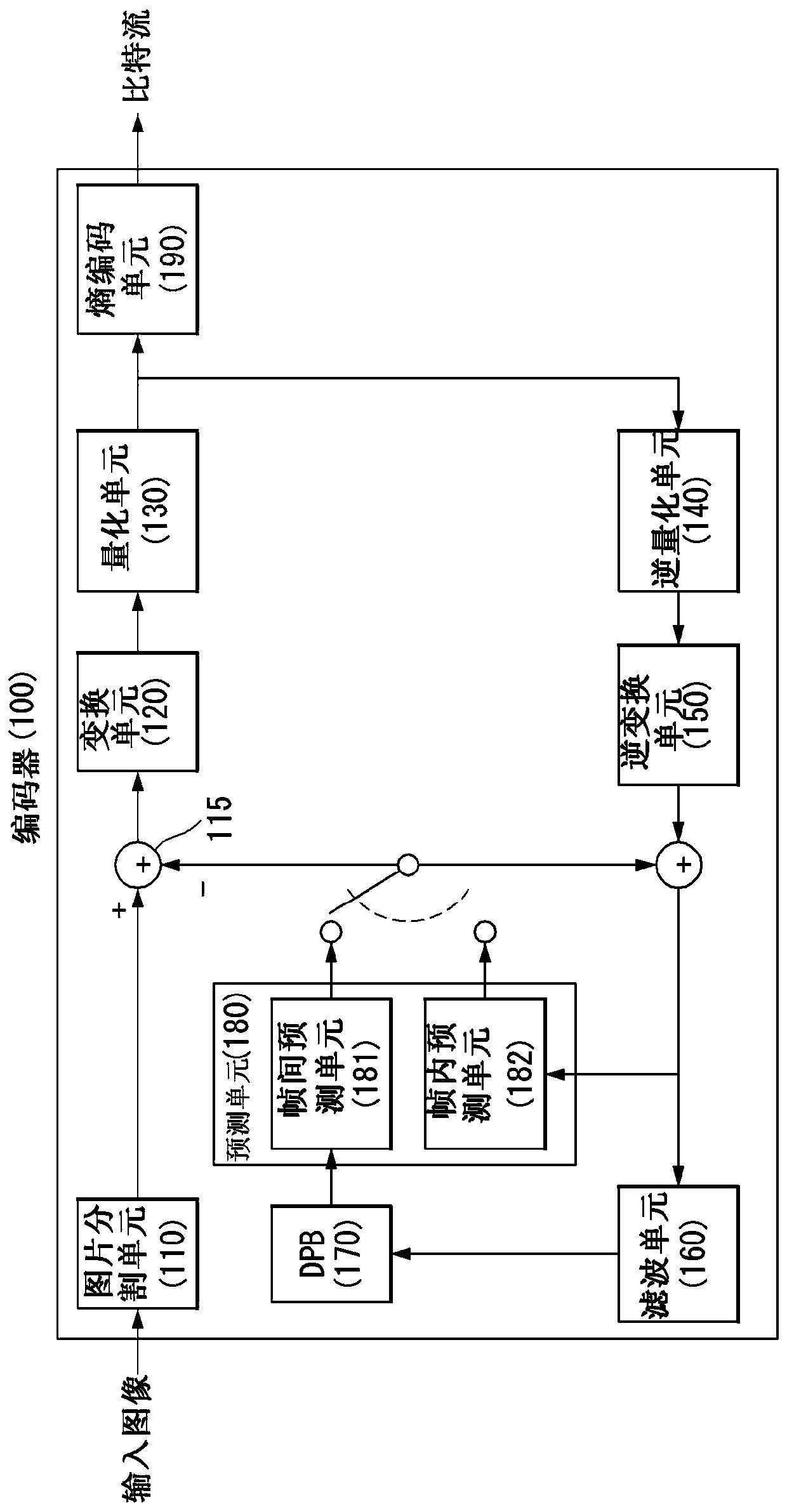
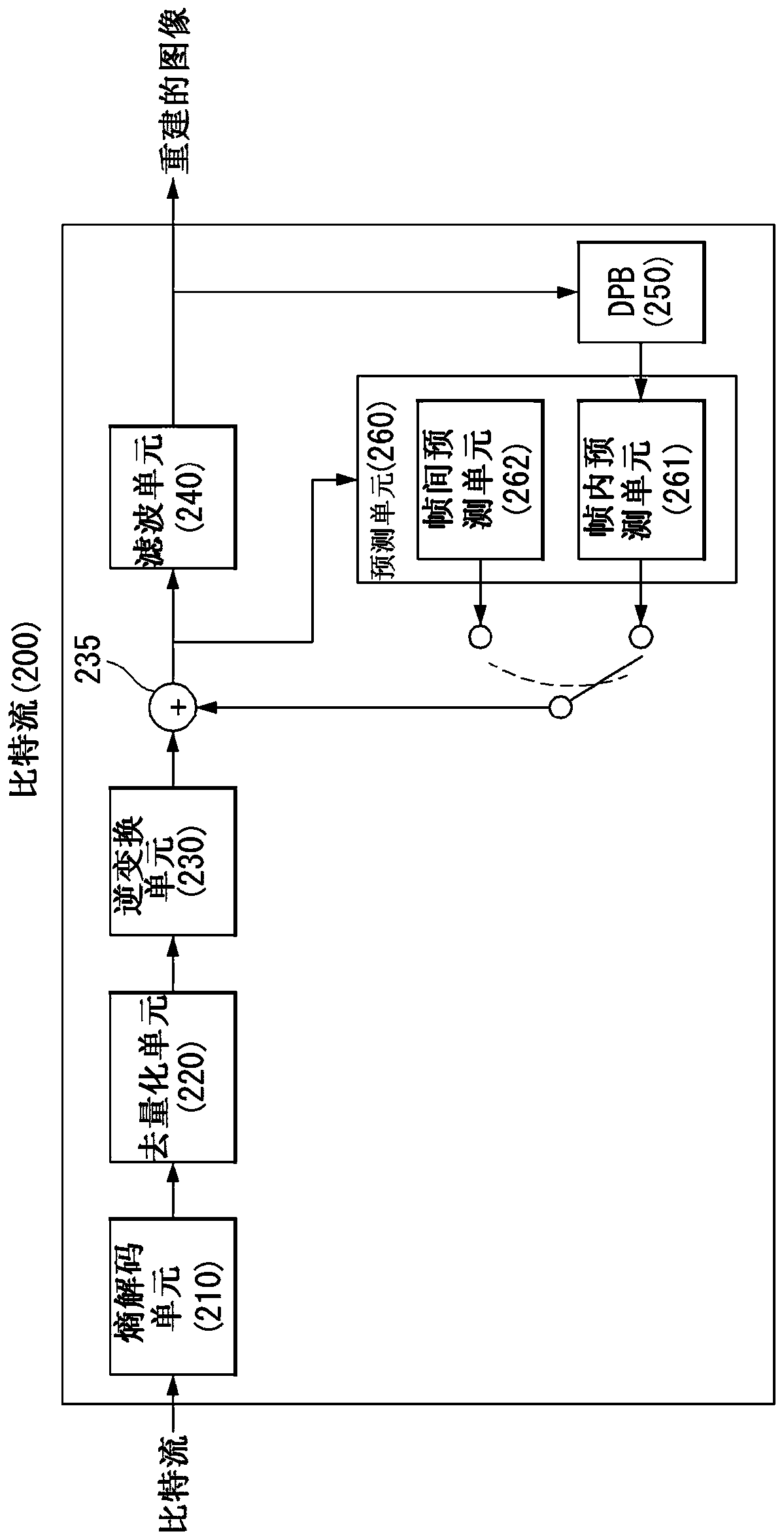
[0152] In an embodiment of the present disclosure, an encoder / decoder may hierarchically configure a scanning order of transform coefficients. In other words, the encoder / decoder may divide the transform block (or residual block or scan processing block) into coefficient groups, and then perform scanning in units of the divided coefficient groups. Groups of coefficients may be referred to as sub-blocks, sub-groups, sub-groups of coefficients, and the like.
[0153] The encoder / decoder may scan the transform coefficients in each coefficient group while scanning the transform coefficients in units of coefficient groups divided from the transform block according to the scanning order. For example, a coefficient group may be a block with a size of 4x4. will refer to the following Figure 7 Describe it.
[0154] Figure 7 is a diagram illustrating a method for scanning transform coefficients in units of coefficient groups as an embodiment to which the present disclosure is appl...
Embodiment 2
[0214] In an embodiment of the present disclosure, the encoder / decoder may determine the scanning order of each coefficient in the coefficient group based on the size or shape of the coefficient group. That is, the encoder / decoder may determine the scan order of the coefficients in the coefficient group of Equation 2 above according to the size or shape of the block.
[0215] Figure 12 and Figure 13 is a diagram illustrating a scan order depending on the position of transform coefficients in a block according to an embodiment of the present disclosure.
[0216] refer to Figure 12 , the encoder / decoder can scan the coefficients in the order of increasing d values in diagonal scan order. Here, d represents the distance of the corresponding coefficient based on the upper left coefficient. The encoder / decoder may scan coefficients at positions having the same d value from the lower left side to the upper right side.
[0217] Here, the value of d can be determined as d=dx...
Embodiment 3
[0262] In an embodiment of the present disclosure, a method for determining a scan order of coefficient groups is proposed. For example, an encoder / decoder can determine for Figure 9 (c) constitute CG 1 The scan order of the four coefficient groups of (1,1).
[0263] The encoder / decoder can scan scan groups in a diagonal scan order, such as Figure 9 As shown in (c). In addition, the encoder / decoder may apply the scan method described in Examples 1 and 2 above when determining the scan order between coefficient groups, and apply the scan order with a random order.
[0264] Figure 18 is a diagram illustrating a method for determining a scanning order of coefficient groups as an embodiment to which the present disclosure is applied.
[0265] refer to Figure 18 , the encoder / decoder may be configured to similarly use the scanning order of the coefficient groups and the scanning order of the coefficients within the coefficient group, or be configured to use each scanning ...
PUM
 Abstract
Description
Claims
Application Information
 - R&D
- Intellectual Property
- Life Sciences
- Materials
- Tech Scout
- Unparalleled Data Quality
- Higher Quality Content
- 60% Fewer Hallucinations
Browse by: Latest US Patents, China's latest patents, Technical Efficacy Thesaurus, Application Domain, Technology Topic, Popular Technical Reports.
© 2025 PatSnap. All rights reserved.Legal|Privacy policy|Modern Slavery Act Transparency Statement|Sitemap|About US| Contact US: help@patsnap.com


