
Transmission and display of video data

a video data and video technology, applied in the field of video data transmission and display systems, can solve the problems affecting the quality of video data, so as to achieve the effect of reducing the quantity reducing the number of data to be transmitted, and sharpening the vision

Inactive Publication Date: 2005-10-25
SWISSCOM
View PDF14 Cites 31 Cited by
  • Summary
  • Abstract
  • Description
  • Claims
  • Application Information

AI Technical Summary

Benefits of technology

[0006]It is an object of this invention to propose a new and better system, a new and better method and suitable devices for transmitting and presenting video data which in particular make possible shorter transmission times during transmission over a telecommunications network.
[0008]In the system for transmitting and presenting video data which includes a video center with a communications module as well as a telecommunications network with at least one communications terminal connected thereto, the video center being able to transmit by means of the communications module video data via the telecommunications network to a communications terminal, this communications terminal comprising at least one video display device that presents received video data to the user of the communications terminal in a visible way, and which includes an eye position tracking module that determines current eye positions of the user, and the communications terminal including an eye position feedback module that transmits the determined current eye positions to the video center, this object is achieved through the invention in particular by the video center including a database and / or a file server with digital video data, by the video display device being a virtual retinal display device (Virtual Retinal Display, VRD), which projects picture signals corresponding to the received video data onto the retina of the said user, and by the video center including a video filter module, which filters the video data, prior to their transmission, on the basis of received current eye positions such that outer picture regions, corresponding to the video data, which are projected onto the retina outside the fovea, have a lower resolution than inner picture regions, corresponding to the video data, which are projected on the fovea of the retina. Moreover the filtered video data therefore contain a lesser data quantity than the unfiltered video data. The advantage of this system and of the corresponding method consists in that a particular characteristic of the human eye, i.e. the fact that a small region of the retina having an optic angle of approximately 2°, the so-called fovea, has the sharpest vision, can be exploited in such a way that the quantity of data to be transmitted can be drastically reduced.
[0009]In an embodiment variant, the telecommunications network includes a mobile network, for instance a mobile radio network for mobile telephony, e.g. a GSM or UMTS network, and the communications terminals are mobile radio devices, for instance a mobile radio telephone or a communication-capable laptop or palmtop computer. This has the advantage that mobile users can obtain video data from the video center and view video data by means of the video display device of their mobile devices, the video center not having to be directly connected to the mobile network, but being able to be reached over the mobile network via suitable network units, such as, for example, a Mobile Switching Center (MSC) or a Short Message Service Center (SMSC).
[0010]In an embodiment variant, the video filter module has a cut-out function which filters out at least certain of the said video data corresponding to the above-mentioned outer picture regions so that the picture region corresponding to the filtered video data is a section from the picture region corresponding to the unfiltered video data, which section contains at least the inner picture region. This has the advantage that, in particular with a large total picture area, only those video data that are viewed by the user in detail have to be transmitted with a high resolution.
[0011]In an embodiment variant, the video center includes a prediction module which stores eye positions determined by the eye position tracking module, and which predicts a subsequent eye position on the basis of these stored eye positions. This has the advantage that the number of reports of eye positions to the video center, in particular with continuous change of the eye positions of the user, can be reduced, it being possible to increase it in the case of extreme change in eye positions, for example. In a further variant, the content of the video data can additionally be taken into consideration in the prediction of a subsequent eye position, so that the change in the eye position correlates with the movement of large and / or central objects, for instance.
[0012]In an embodiment variant, a correction module receives correction values from the user, stores received correction values, and corrects eye positions, determined by the eye position tracking module, with stored correction values. This has the advantage that the agreement of determined eye positions with the position of the fovea of the user can be adjusted by the user by entering the correction values such that the picture region with the highest resolution is actually projected on the fovea.

Problems solved by technology

Nevertheless the transmission times for video data are considered too slow by many users.
Moreover, there are complaints that one is dependent upon a fixed-installed personal computer in particular during simultaneous download and visible reproduction of video data.

Method used


Image

  • Transmission and display of video data
  • Transmission and display of video data

Examples


Embodiment Construction

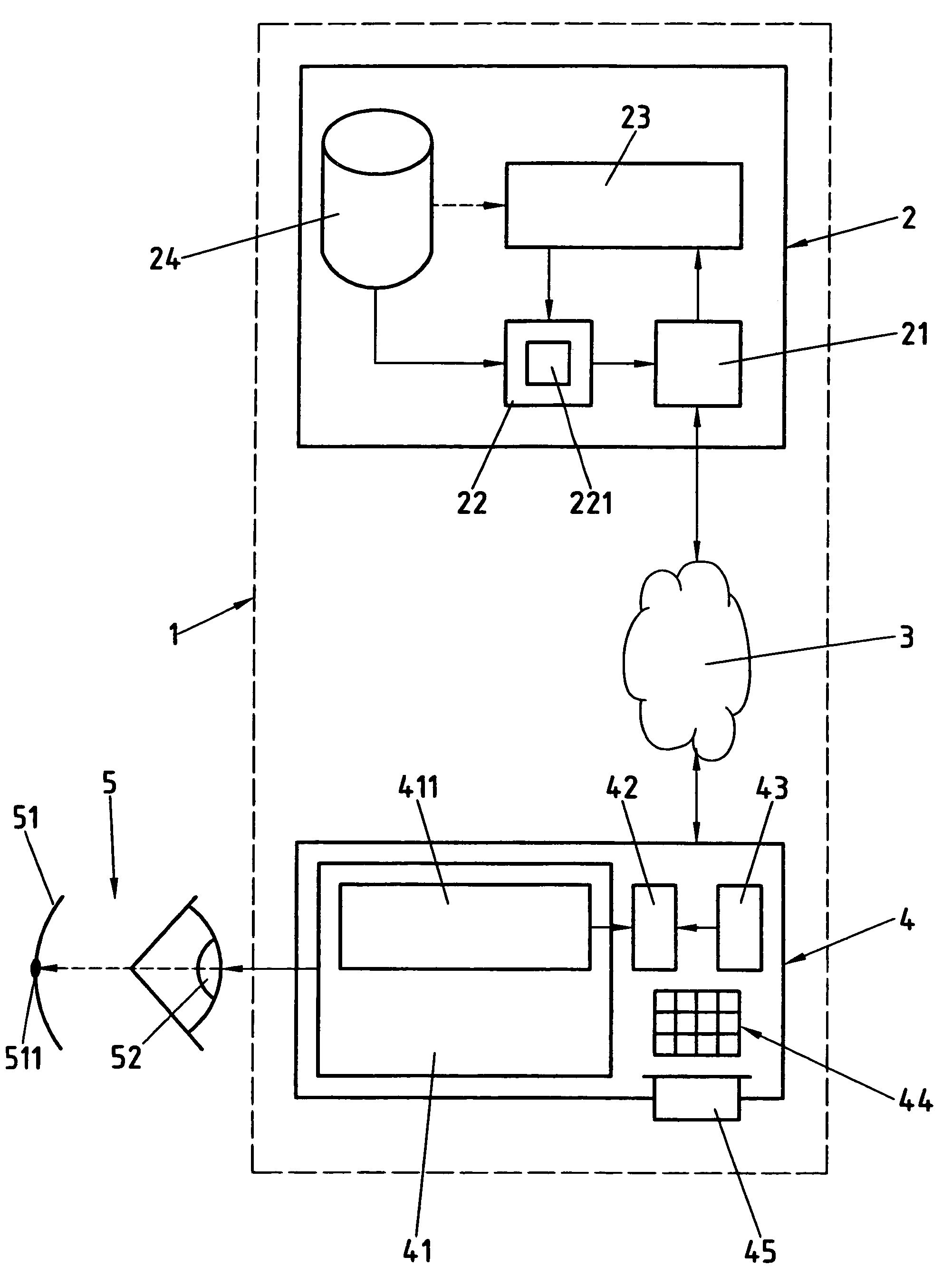
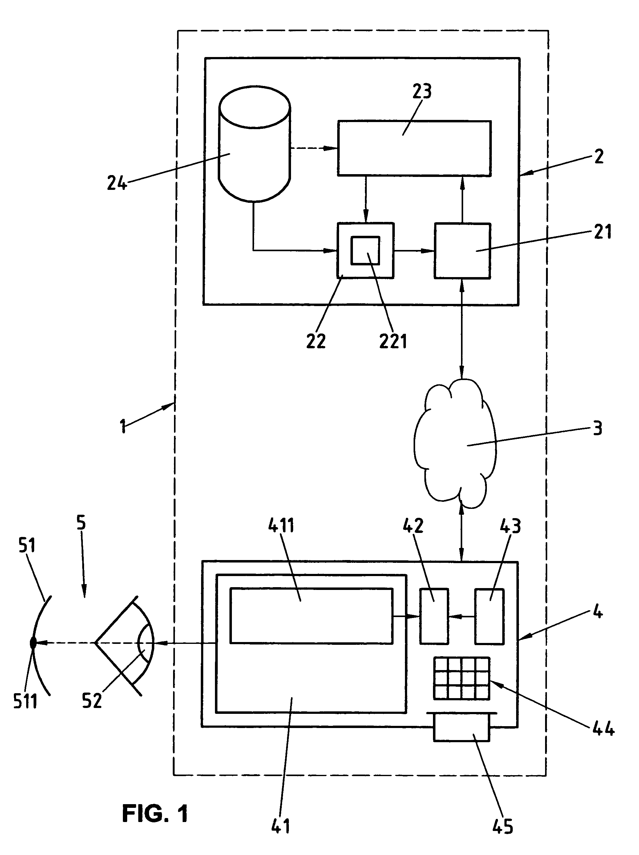
[0015]An embodiment of the present invention will be described in the following with reference to an example. The example of the embodiment is illustrated by the following single attached figure:

[0016]FIG. 1 shows a block diagram of the system, showing schematically a video center which is connected via a telecommunications network to a communications terminal including a video display device that projects video data onto the retina of an eye.

[0017]The reference numeral 1 in FIG. 1 relates to a system for transmitting and presenting video data, i.e. digital data files the content of which can be shown to an interested user as moving pictures using suitable reproduction means, in which system 1 these video data are obtained from a video center 2 and are transmitted over a telecommunications network 3 to a communications terminal 4, where, through a video display device 41 of the communications terminal 4, picture signals corresponding to the video data are projected onto the retina 5...


PUM


Abstract

A system (1) and a method for transmitting and presenting video data as well as a communications terminal (4) suitable therefor and a suitable video center (2), users being able to request and obtain video data from the video center (2) by means of communications terminals (4), in particular mobile communications terminals (4), over a telecommunications network (3), in particular a mobile radio network (3), picture signals corresponding to the received video data being projected upon the retina (51) of the user through a virtual retina display device (41) of the communications terminal (4), current eye positions of the user being determined in the communications terminal (4) and being transmitted to the video center (2), and the video center (2) comprising a video filter module which filters said video data, prior to their transmission, on the basis of received current eye positions such that outer image regions, corresponding to the video data, projected on the retina (51) outside the fovea (511) have a lesser resolution than the inner image areas, corresponding to the video data, projected on the fovea (511) of the retina (51), and the filtered video data accordingly contain a lesser quantity of data than the unfiltered video data.

Description

BACKGROUND OF THE INVENTION[0001]1. Field of the Invention[0002]This invention relates to a system and a method for transmitting and presenting video data as well as devices suitable therefor. In particular, this relates to a system and method for transmitting and presenting video data as well as devices suitable therefor according to the preamble of the respective independent claim 1, 7, 13 or 16.[0003]2. Description of the Related Art[0004]Especially with the spread of the Internet, it has become more and more popular to offer over the Internet video data, i.e. files with digital data that, with suitable playback means, can be presented to the user as moving pictures, to download them from the Internet, and show them on the screen of a personal computer, or store them in a data store of a personal computer. In order to reduce the required transmission times and storage capacities for the digital video data, the video data are typically stored and transmitted in compressed form, an...

Claims


Application Information

Patent Timeline
IPC IPC(8): G02B27/01G09G5/00H04N7/26H04N7/14H04N7/24H04L29/06H04N7/173H04N5/64H04N1/41
CPCH04N7/17318H04N21/234363H04N21/44213H04N21/4621H04N21/6582G02B27/0093
Inventor RITTER, RUDOLFLAUPER, ERIC
Owner SWISSCOM
Learn More