Bidirectional automatic variable-speed motor transmission device

A technology of motor transmission and automatic speed change, applied in the field of machinery, can solve problems such as the loose structure of the two-way automatic speed change motor transmission mechanism, and achieve the effects of improving work stability, reducing distance, and working stably

Active Publication Date: 2015-10-14
屠申富 +1
View PDF7 Cites 28 Cited by
  • Summary
  • Abstract
  • Description
  • Claims
  • Application Information

AI Technical Summary

Problems solved by technology

But there is a problem in this transmission mechanism: the backward one-way device is distributed on one side of the automatic transmission shaft, and the forward one-way device is distributed on the axis of the automatic transmission shaft, and there

Method used


Image

  • Bidirectional automatic variable-speed motor transmission device
  • Bidirectional automatic variable-speed motor transmission device
  • Bidirectional automatic variable-speed motor transmission device

Examples


Embodiment 1

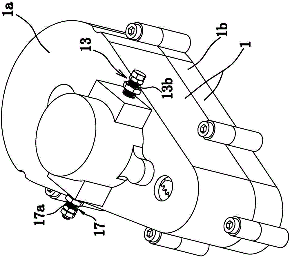
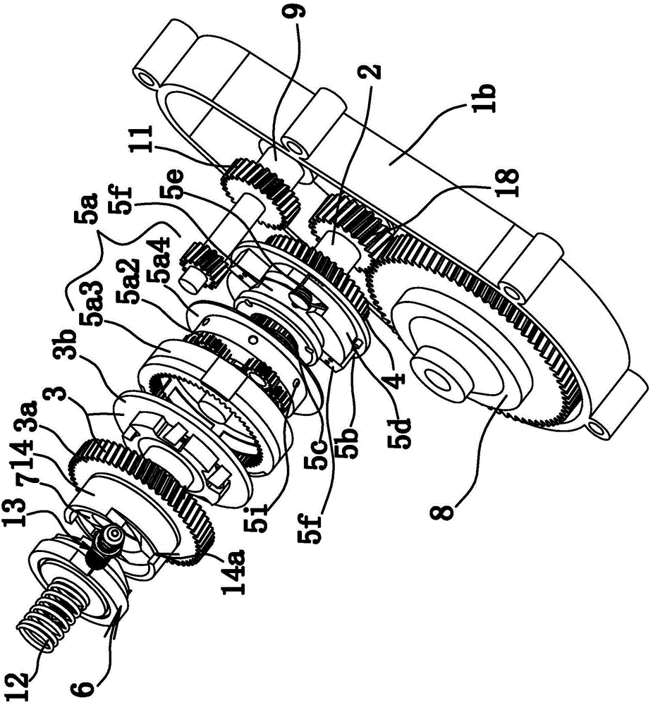
[0075] Such as Figure 1 to Figure 4 As shown, the bidirectional automatic variable speed motor transmission device is composed of a housing 1, a main shaft 2, a one-way device 3, a gear 4, a speed change mechanism 5, a transmission part 6, a connecting part 7, a differential 8 and the like. Wherein, the main shaft 2 is a spline shaft. Such as figure 1 As shown, the housing 1 includes an upper half shell 1a and a lower half shell 1b that are fixedly connected.

[0076] The main shaft 2 is axially fixed in the housing 1; the gear 4 and the main shaft 2 are axially fixed, that is, the gear 4 can rotate circumferentially relative to the main shaft 2; the one-way device 3 is sleeved on the main shaft 2. Wherein, the one-way device 3 includes an outer ring 3 a with outer teeth and an inner ring 3 b fixed to the main shaft 2 . In this embodiment, the one-way device 3 is a roller-type one-way clutch, and the structure between the inner ring 3b and the outer ring 3a is the same as ...

Embodiment 2

[0097] The structure and principle of the second embodiment are basically the same as those of the first embodiment, except that the limiter 13 includes a limiter 13a that is against the end surface of the stop edge 6c1 close to the outer ring 3a and a limiter 13a that can be driven Electromagnet 1 that translates toward or away from the main shaft 2, and electromagnet 1 is fixed to the housing 1; the coupling mechanism does not include a retreat structure, and other parts of the coupling mechanism are the same as in Embodiment 1; the separation mechanism does not include an advancing structure, And the other parts of the separation mechanism are the same as those in Embodiment 1.

Embodiment 3

[0099] The structure and principle of this third embodiment are basically the same as that of the first embodiment, except that the guide assembly includes a guide portion 7a, an inclined surface 7a1 facing the transmission part 6, and a protruding part on the end surface of the transmission part 6. Straight rod-shaped support portion. When the guide part 2 6a is plugged into the socket, the support part abuts against the inclined surface 1 7a1. When the rotating shaft 9 rotates clockwise, the supporting part moves along the inclined surface 7a1, so that the rotation of the connecting part 7 is converted into the axial movement of the transmission part 6, and drives the abutting part to overcome the elastic force of the compression spring 12 and protrude out of the socket. Make the connecting piece 7 and the transmission piece 6 in the disengaged state. By setting the guide assembly as the inclined surface 7a1 on the guide part 7a and the support part on the transmission part...


PUM


Abstract

The invention provides a bidirectional automatic variable-speed motor transmission device and belongs to the technical field of machines. The bidirectional automatic variable-speed motor transmission device solves the problem that an existing bidirectional automatic variable-speed motor transmission device is incompact in structure. The bidirectional automatic variable-speed motor transmission device comprises a shell, a main shaft and a rotary shaft, wherein both the main shaft and the rotary shaft are fixed in the shell in the axial direction. The main shaft is sleeved with a one-way device. The one-way device comprises an outer ring and an inner ring which is fixed to the main shaft. A gear is fixed to the main shaft in the axial direction. A connecting piece is fixed to the outer ring. A transmission piece is fixed to the main shaft in the circumferential direction. The rotary shaft drives the outer ring and the gear to rotate at the same time through a transmission mechanism. The transmission ratio of the rotary shaft to the outer ring is lager than that of the rotary shaft to the gear. When the rotary shaft rotates anticlockwise, the one-way device slips, and the connecting piece is in linkage with the transmission piece through a combining mechanism; when the rotary shaft rotates clockwise, the connecting piece and the transmission piece are separated from each other through a separating mechanism; when the rotary shaft rotates clockwise at a high speed, the gear is in linkage with the inner ring through a speed change mechanism. The bidirectional automatic variable-speed motor transmission device has the advantage of being compact in structure.

Description

technical field [0001] The invention belongs to the technical field of machinery, and relates to a transmission device, in particular to a bidirectional automatic variable speed motor transmission device. Background technique [0002] At present, brushless hub motors, brushless differential motors and series-excited motors used in electric tricycles and electric vehicles are relatively common. Among these three types of motors, because their design takes into account the speed and load of electric tricycles and electric vehicles. Reasonable balance of the above factors, so there is a lack of climbing and speed during use, and the starting current is large, which reduces the service life of the battery, resulting in the amplification of the motor power and energy waste, as well as the load, speed, and climbing. The demand cannot be met. [0003] For this situation, people have realized this deficiency and made improvements, such as a two-way automatic variable speed motor tr...

Claims


Application Information

Patent Timeline
IPC IPC(8): F16H3/44F16H57/023
CPCF16H3/44F16H57/023F16H2003/445F16H2200/00
Inventor 屠申富屠昌德
Owner 屠申富
Why Eureka
Try Eureka