

System and Method for High-Speed Robotic Cladding of Metals
a robotic and robotic technology, applied in the field of metal cladding, can solve the problems of limiting the use of clad steel in a variety of applications and industries, the current cost of clad steel limits the use of clad steel in high corrosion applications, and the cost of clad steel for high corrosion applications is about five times the cost of carbon steel, so as to reduce the impact on the environment, reduce the amount of energy, and reduce the effect of labor
- Summary
- Abstract
- Description
- Claims
- Application Information
AI Technical Summary
Benefits of technology
Problems solved by technology
Method used
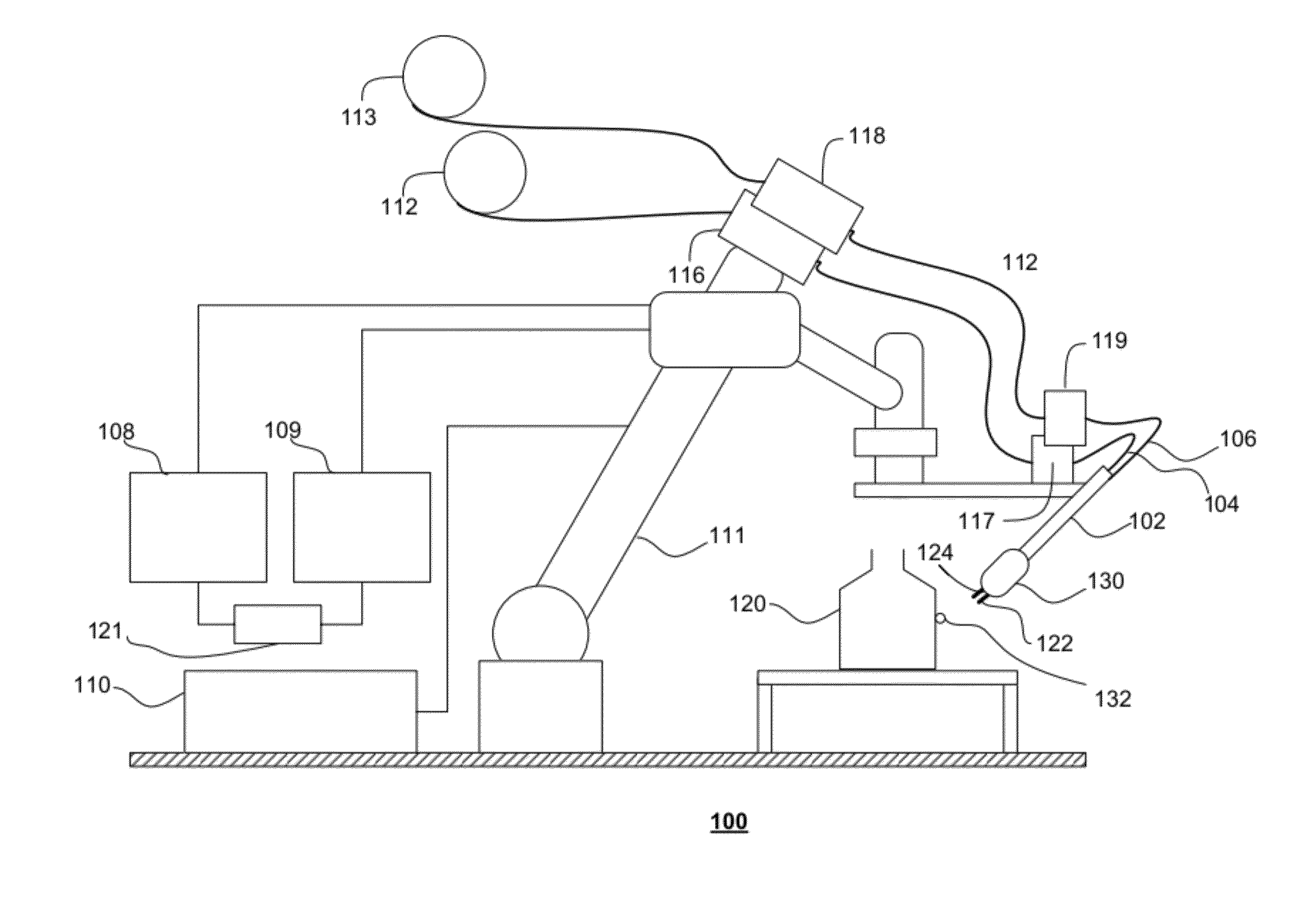
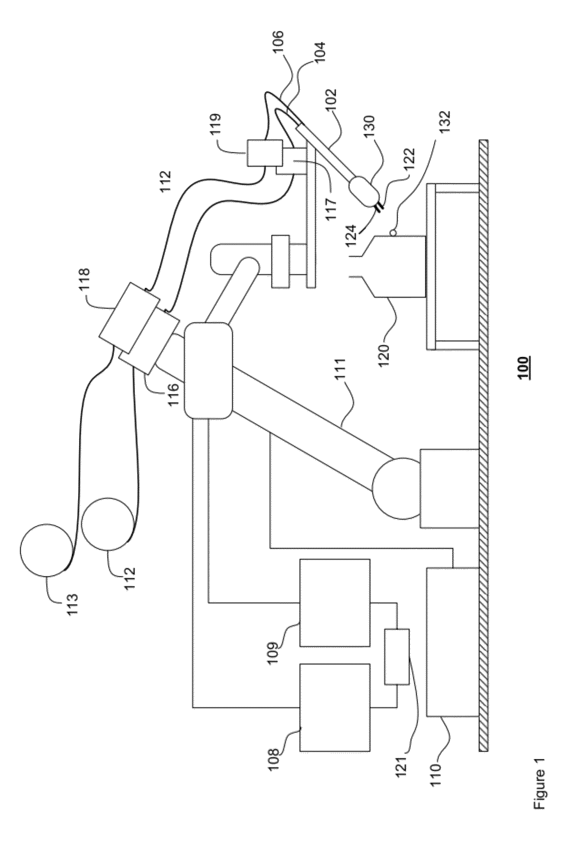
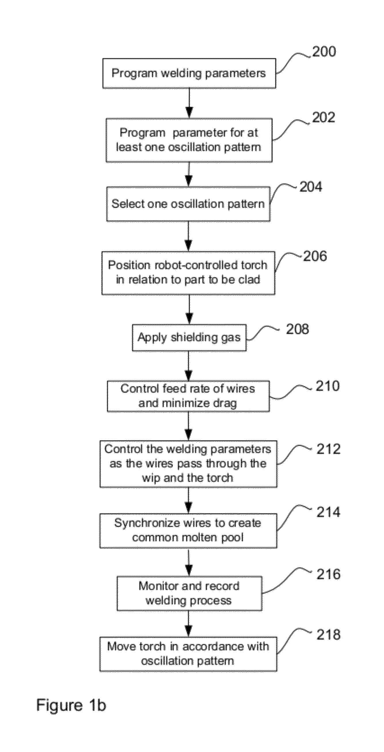
Image

Examples
Embodiment Construction
[0060]The detailed description of exemplary embodiments of the invention herein makes reference to the accompanying block diagrams and schematic diagrams, which show the exemplary embodiment by way of illustration and its best mode. While these exemplary embodiments are described in sufficient detail to enable those skilled in the art to practice the invention, it should be understood that other embodiments may be realized and that logical and mechanical changes may be made without departing from the spirit and scope of the invention. Thus, the detailed description herein is presented for purposes of illustration only and not of limitation. For example, the steps recited in any of the method or process descriptions may be executed in any order and are not limited to the order presented.
[0061]Moreover, it should be appreciated that the particular implementations shown and described herein are illustrative of the invention and its best mode and are not intended to otherwise limit the ...
PUM
| Property | Measurement | Unit |
|---|---|---|
| speed | aaaaa | aaaaa |
| travel speed | aaaaa | aaaaa |
| weave angle | aaaaa | aaaaa |
Abstract
Description
Claims
Application Information