
Wire grid polarizer, display device including the same, and method of fabricating the wire grid polarizer

Active Publication Date: 2015-04-02
SAMSUNG DISPLAY CO LTD
View PDF1 Cites 7 Cited by
  • Summary
  • Abstract
  • Description
  • Claims
  • Application Information

AI Technical Summary

Benefits of technology

The present invention provides a wire grid polarizer with spaces filled with air, a display device including the wire grid polarizer, and a method of fabricating the wire grid polarizer. The technical effect is improved optical performance and reduced cost of the wire grid polarizer.

Problems solved by technology

Because the wire grid structure is formed of a conductive material, it may react with an electrode, etc., inside a display device, thus causing the display device to malfunction.

Method used


Image

  • Wire grid polarizer, display device including the same, and method of fabricating the wire grid polarizer
  • Wire grid polarizer, display device including the same, and method of fabricating the wire grid polarizer
  • Wire grid polarizer, display device including the same, and method of fabricating the wire grid polarizer

Examples


Embodiment Construction

[0028]The present invention will be described more fully hereinafter with reference to the accompanying drawings, in which exemplary embodiments of the invention are shown. This invention may, however, be embodied in many different forms and should not be construed as being limited to the embodiments set forth herein. Rather, these embodiments are provided so that this disclosure is thorough, and will fully convey the concept of the invention to those skilled in the art. In the drawings, the size and relative sizes of elements may be exaggerated for clarity. Like reference numerals in the drawings denote like elements.

[0029]The terminology used herein is for the purpose of describing particular embodiments only and is not intended to be limiting of the invention. As used herein, the singular forms “a”, “an” and “the” are intended to include the plural forms as well, unless the context clearly indicates otherwise. It will be further understood that the terms “comprises” and / or “compr...


PUM


Abstract

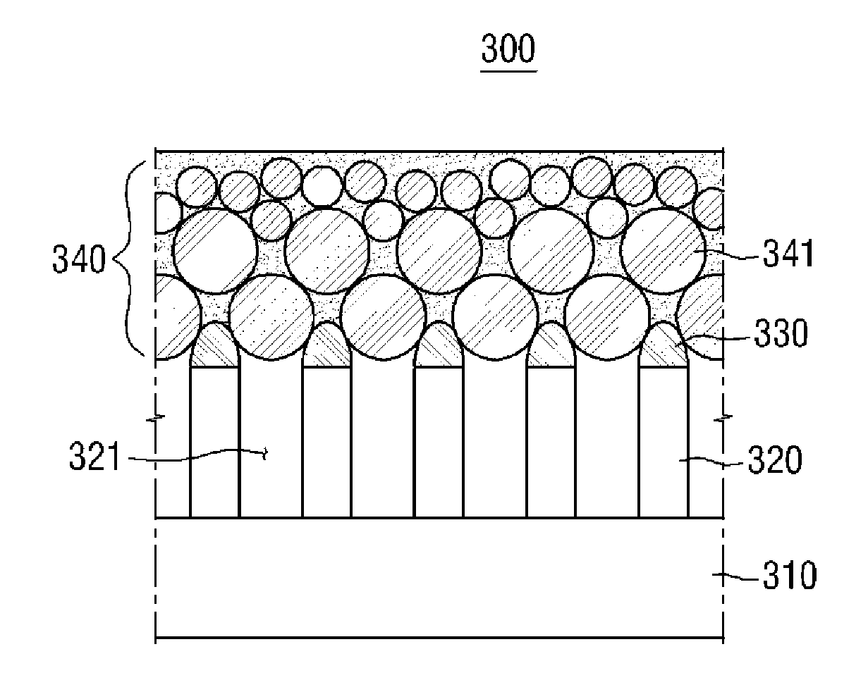
A wire grid polarizer including a substrate, parallel conductive wire patterns which protrude from a top surface of the substrate, non-conductive wire patterns which are formed on the conductive wire patterns, respectively, and a protective layer which is formed on the conductive wire patterns and the non-conductive wire patterns. The protective layer includes first transparent particles having a diameter greater than a period of the conductive wire patterns, and spaces between the conductive wire patterns are filled with air or are evacuated to form a vacuum.

Description

CROSS-REFERENCE TO RELATED APPLICATION[0001]This application claims priority from and the benefit of Korean Patent Application No. 10-2013-0117882, filed on Oct. 2, 2013, which is hereby incorporated by reference for all purposes as if fully set forth herein.BACKGROUND[0002]1. Field[0003]Exemplary embodiments of the present invention relate to a wire grid polarizer, a display device including the same, and a method of fabricating the wire grid polarizer.[0004]2. Discussion of the Background[0005]A wire grid consists of parallel conductive wires arranged to transmit only light of is a specific polarization, from among electromagnetic waves transmitted thereto.[0006]A wire grid structure having a period smaller than a wavelength of received unpolarized light, reflects light polarized in the direction of wires, and transmits light polarized in a direction perpendicular to the wires. Thus, the wire grid structure has the advantage in that the reflected polarized light may be reused, unl...

Claims


Application Information

Patent Timeline
IPC IPC(8): G02F1/1335G02B1/10G02B1/12G02B5/30
CPCG02F1/133528G02B5/3058G02F2001/133548G02B1/12G02B1/105G02B27/0006G02F1/133548G02B5/30G02F1/1335
Inventor TAKAKUWA, ATSUSHINAM, JUNG GUNAN, MOON JUNGKIM, EUN JUNGJO, GUG RAE
Owner SAMSUNG DISPLAY CO LTD
Learn More