Containment berm with internal "l" braces

a technology of containment berms and l-shaped braces, which is applied in the direction of rigid containers, transportation and packaging, swimming pools, etc., can solve the problems of weak spots, weak spots, and unnecessary man-hours constantly pulling

Active Publication Date: 2015-04-09
CUSTOM CHEM SOLUTIONS
View PDF26 Cites 10 Cited by
  • Summary
  • Abstract
  • Description
  • Claims
  • Application Information

AI Technical Summary

Problems solved by technology

This type of system suffers from a number of disadvantages, however.
This leads to unnecessary man hours constantly pulling the “A” braces and berm walls back out and into place.
Multiple sand/weight bags are required with these types of systems, which is yet another drawback.
As noted above, the rods that run through the hem are not interconnected; therefore, there is no corner-to-corner support, resulting in weak spots in the event of a spill.

Method used


Image

  • Containment berm with internal "l" braces
  • Containment berm with internal "l" braces
  • Containment berm with internal "l" braces

Examples


Embodiment Construction

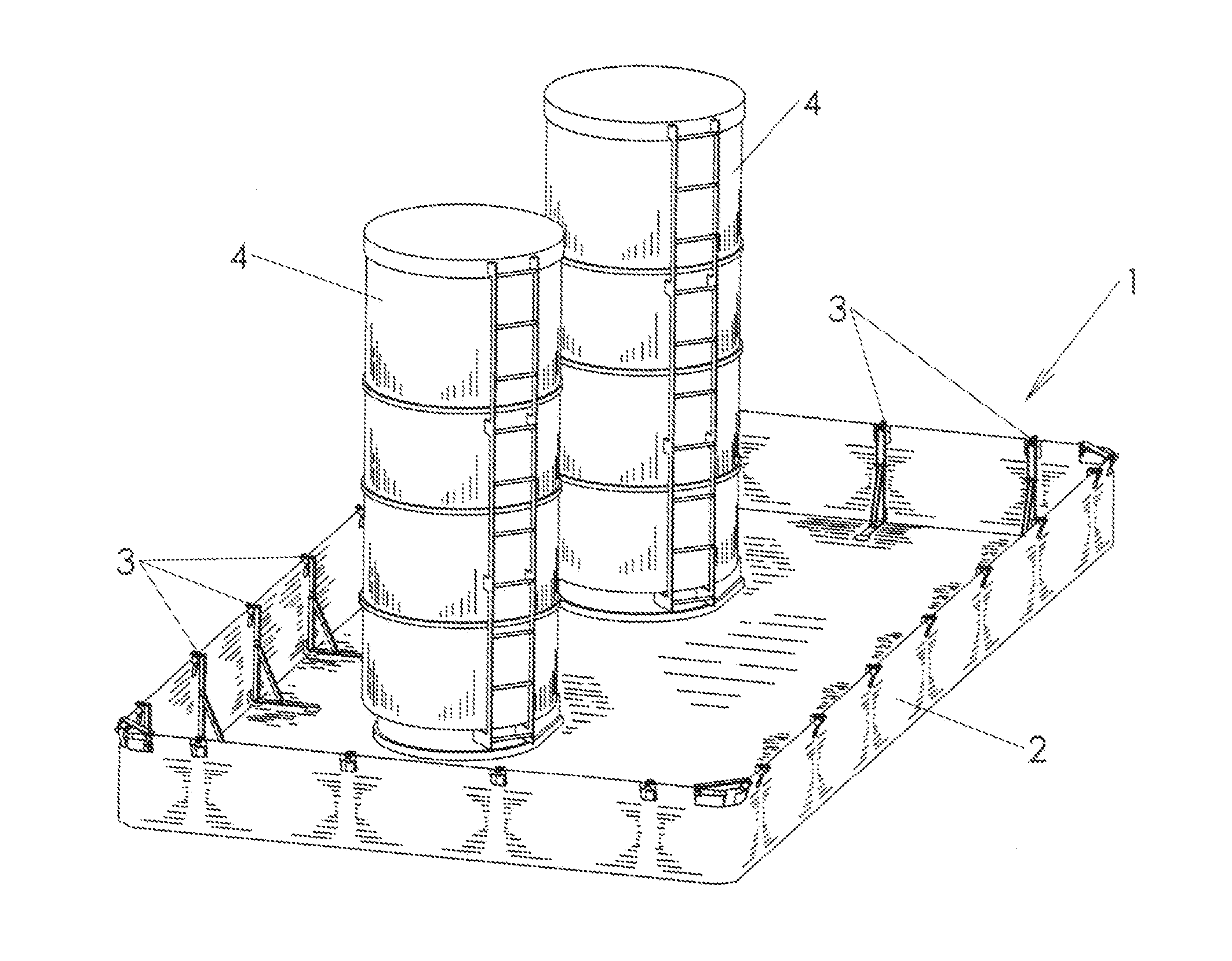
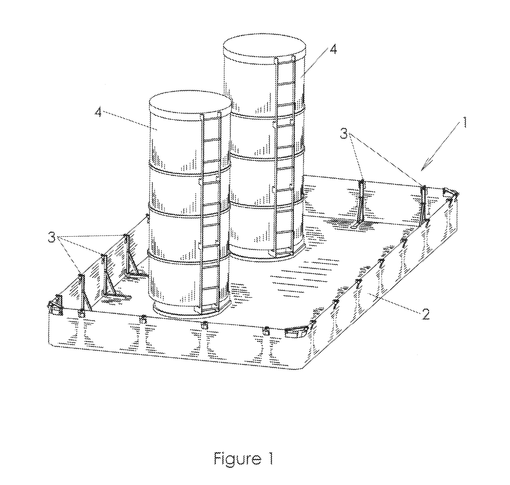
[0056]FIG. 1 is a perspective view of the containment berm fully assembled and with two tanks positioned within the berm. As shown in this figure, the containment berm 1 is comprised of a containment material 2 that is preferably durable, flexible and chemically resistant. One example of a suitable material is XR-5™ manufactured and sold by Seaman Corporation of Wooster, Ohio. The containment material 2 is configured to provide a floor and four side walls (or two side walls and two end walls). A plurality of internal “L” braces 3 is positioned on the inside of the berm, and a top rail 14 (see FIG. 4) extends around the perimeter of the berm 1 (along the top of the side walls / end walls). In a preferred embodiment, the internal “L” braces are spaced every five to six feet along the side / end walls. As shown in subsequent figures, the bottom ends of the internal “L” braces fit into pockets in the floor of the berm, and the top ends of the braces clamp onto the top rail 14. The purpose o...


PUM


Abstract

A containment berm comprising a containment material that is configured to provide at least a floor and four walls of the berm, a plurality of brackets positioned on the floor and adjacent to the inside surface of the four walls, and a top rail. Each bracket comprises a vertical member, connecting member, and horizontal member. A first end of the vertical member is pivotally connected to a first end of the horizontal member at a first pivot point. A first end of the connecting member is pivotally connected to the horizontal member at a second pivot point between the first and second ends of the horizontal member. The top rail extends around a top perimeter of the four walls of the berm. Each bracket comprises a clamp portion that is situated on a second end of the vertical member and that clamps onto the top rail.

Description

BACKGROUND OF THE INVENTION[0001]1. Field of the Invention[0002]The present invention relates generally to the field of containment berms, and more specifically, to a containment berm with internal “L” braces that are removably coupled to a top rail extending around the upper perimeter of the berm and also to a flexible, durable and chemically resistant material that terms the body of the berm.[0003]2. Description of the Related Art[0004]Oil drilling rigs use large, portable secondary containment berms to contain tank farms consisting of multiple 400 BBL (16,800 gallon) upright tanks. These conventional containment berms are typically comprised of a heat-welded geomembrane liner that is configured to provide a three-foot sidewall supported by “A” braces on the exterior side of the berm. These “A” braces connect to segments of steel rod that run partially through the hem of the geomembrane liner and that are not connected to one another.[0005]This type of system suffers from a number...

Claims


Application Information

Patent Timeline
IPC IPC(8): B65D90/24
CPCB65D90/24B65D90/205E04H4/0018E04H4/0056E04H2004/146
Inventor LAING, CHARLES R.ROEMMICH, RYAN L,SPOMER, REUBEN J,
Owner CUSTOM CHEM SOLUTIONS
Why Eureka
Try Eureka