Liquid ejection device and liquid leakage suppression method

Active Publication Date: 2015-04-09
CANON KK
View PDF2 Cites 20 Cited by
  • Summary
  • Abstract
  • Description
  • Claims
  • Application Information

AI Technical Summary

Benefits of technology

The objective of this invention is to prevent liquid from leaking from a machine or device.

Problems solved by technology

The liquid leaking from the head may adversely affect a main body of the liquid ejection device.
However, the liquid ejection device disclosed in Japanese Patent Application Laid-Open No. 2006-192785 has the following problems.
Specifically, the volume of air is liable to vary along with a change in temperature or pressure.
Further, the flexible member forming the ink tank is made of a material which is not capable of preventing the permeation of gas completely.
Therefore, it is difficult to maintain the internal pressure of the head to be a negative pressure, and there has been a risk in that the liquid may leak from the head.
As a result, the pressure of the liquid in the head varies, and there has been a risk in that the liquid may leak from the head.

Method used


Image

  • Liquid ejection device and liquid leakage suppression method
  • Liquid ejection device and liquid leakage suppression method
  • Liquid ejection device and liquid leakage suppression method

Examples


first embodiment

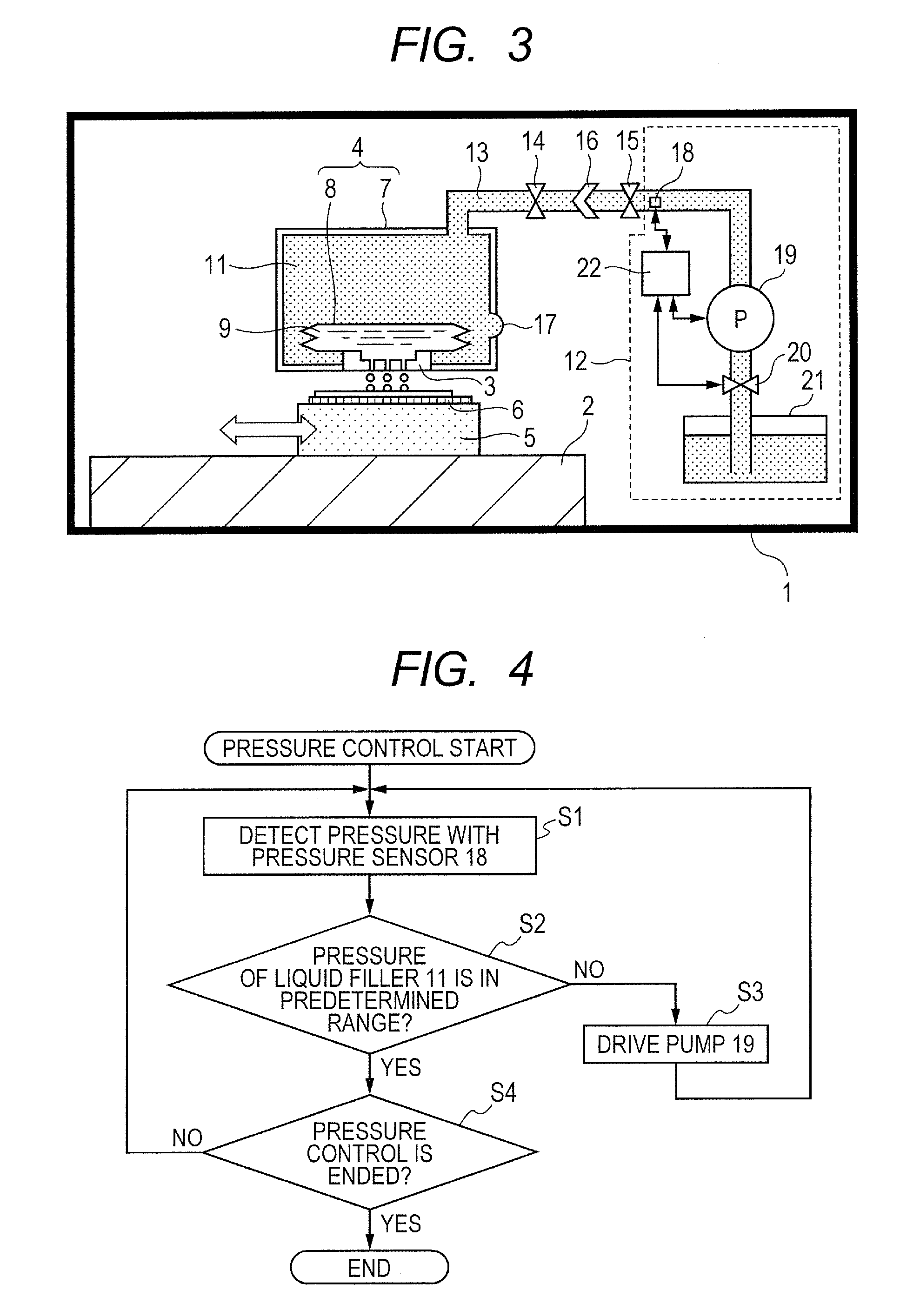
[0046]A first embodiment of the present invention is described with reference to FIGS. 1 to 4.

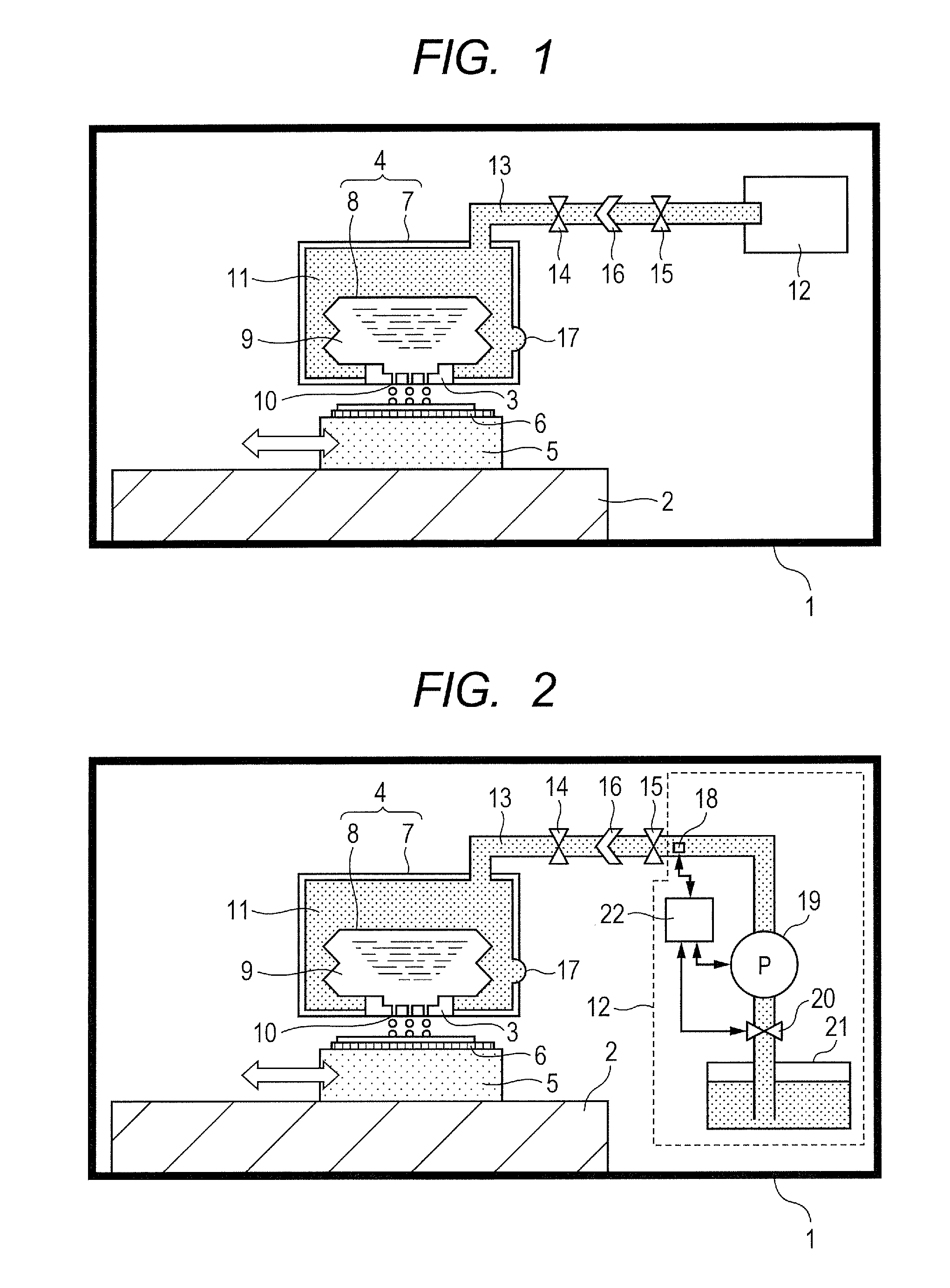
[0047]FIG. 1 is a schematic view of a liquid ejection device according to this embodiment. The liquid ejection device illustrated in FIG. 1 is an inkjet device which ejects ink.

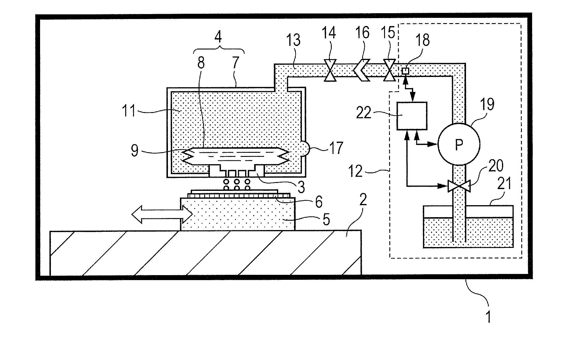
[0048]As illustrated in FIG. 1, a liquid ejection device 1 includes a base plate 2, a head 3, and a liquid containing unit 4. A conveyance portion 5 is mounted on the base plate 2. An object 6 to be printed is attracted onto the conveyance portion 5 through use of an attraction unit (not shown).

[0049]The liquid containing unit 4 includes a sealed housing 7 and a flexible containing bag 8 provided in the housing 7. The housing 7 includes a first containing space communicating with the head 3 and a second containing space partitioned from the first containing space through use of the flexible containing bag 8. The second containing space does not communicate with the head 3.

[0050]In this embodiment, the inner space of ...

second embodiment

[0095]A second embodiment of the present invention is described with reference to FIG. 5. FIG. 5 is a schematic view of a liquid containing unit provided in a liquid ejection device according to this embodiment. Note that, the same elements as those in the first embodiment are denoted by the same reference symbols, and the descriptions thereof are omitted.

[0096]In this embodiment, as illustrated in FIG. 5, the liquid filler 11 is filled into the inner space of the flexible containing bag 8, and the liquid 9 is filled into the space between the outer side surface of the containing bag 8 and the housing 7. That is, the inner space of the flexible containing bag 8 forms a second containing space to be filled with the liquid filler 11, and the space between the outer side surface of the containing bag 8 and the housing 7 forms a first containing space containing the liquid 9. The containing bag 8 communicates with the pressure adjusting unit 12 via the communication unit 13 (see FIG. 1)...

third embodiment

[0099]A third embodiment of the present invention is described with reference to FIG. 6. FIG. 6 is a schematic view of a liquid ejection device according to this embodiment. Note that, the same elements as those in the first embodiment are denoted by the same reference symbols, and the descriptions thereof are omitted.

[0100]The liquid containing unit 4 is formed detachably with respect to a main body of the liquid ejection device 1. Thus, in the case where the liquid containing unit 4 is broken or the case where the liquid 9 contained in the containing bag 8 is consumed completely, the liquid ejection device 1 can be ready to be used again merely by replacing the liquid containing unit 4.

[0101]A joint 16 is formed so as to be separable into two joint portions 16a and 16b. By providing the joint 16 at the communication unit 13, the communication unit 13 can be separated from the pressure adjusting unit 12 between the pressure adjusting unit 12 and the valve 14. As a result, the liqui...


PUM

PropertyMeasurementUnit
Fractionaaaaaaaaaa
Fractionaaaaaaaaaa
Pressureaaaaaaaaaa

Abstract

There is provided a liquid ejection device including a head for ejecting a liquid, a liquid containing unit, a liquid filler, and a pressure adjusting unit, in which the liquid containing unit includes a sealed housing and a flexible member provided in the housing, the housing includes a first containing space communicating with the head and a second containing space partitioned from the first containing space through use of the flexible member, the first containing space contains the liquid, and the liquid filler is filled into the second containing space, the pressure adjusting unit communicates with the second containing space, and adjusts the pressure of the liquid filler filled into the second containing space so as to maintain a negative pressure with respect to the head.

Description

BACKGROUND OF THE INVENTION[0001]1. Field of the Invention[0002]The present invention relates to a liquid ejection device including a liquid ejection head for ejecting a liquid and a method of suppressing the leakage of a liquid from the liquid ejection head.[0003]2. Description of the Related Art[0004]A liquid ejection device including a liquid ejection head (hereinafter simply referred to as “head”) has been known. In recent years, the liquid ejection device has been used in various fields, for example, in an inkjet recording device.[0005]In the liquid ejection device including the head, when the pressure of a liquid in the head increases, the liquid leaks from an orifice of the head. The liquid leaking from the head may adversely affect a main body of the liquid ejection device. For this reason, it is required to maintain the internal pressure of the head to be a negative pressure.[0006]In Japanese Patent Application Laid-Open No. 2006-192785, there is disclosed a liquid ejection...

Claims


Application Information

Patent Timeline
IPC IPC(8): B41J2/20B29C59/16
CPCB41J2/20B29L2031/7678B29C59/16B41J2/01B41J2/175B41J2/17503B41J2/17556Y10T137/0396B41J2002/17516B41J2/17566
Inventor ARAKI, YOSHIMASATAMURA, YASUYUKISAITO, AKIOFUKUHARA, MAKOTOOZAKI, HIROYUKI
Owner CANON KK
Why Eureka
Try Eureka