Method for a part load co reduction operation for a sequential gas turbine

a gas turbine and co reduction technology, applied in the direction of machines/engines, mechanical equipment, lighting and heating apparatus, etc., can solve the problems of over-proportional increase of co production of at least one restricted burner, pulsation in annular combustors, and desired inhomogeneity in annular combustor. , to achieve the effect of reducing co emissions

a gas turbine and co reduction technology, applied in the direction of machines/engines, mechanical equipment, lighting and heating apparatus, etc., can solve the problems of over-proportional increase of co production of at least one restricted burner, pulsation in annular combustors, and desired inhomogeneity in annular combustor. , to achieve the effect of reducing co emissions

US20150101341A1Active Publication Date: 2015-04-16ANSALDO ENERGIA SWITZERLAND AG

Image

  • Method for a part load co reduction operation for a sequential gas turbine
  • Method for a part load co reduction operation for a sequential gas turbine
  • Method for a part load co reduction operation for a sequential gas turbine

Examples


Embodiment Construction

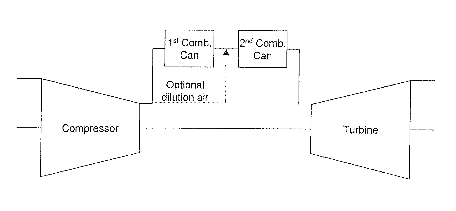
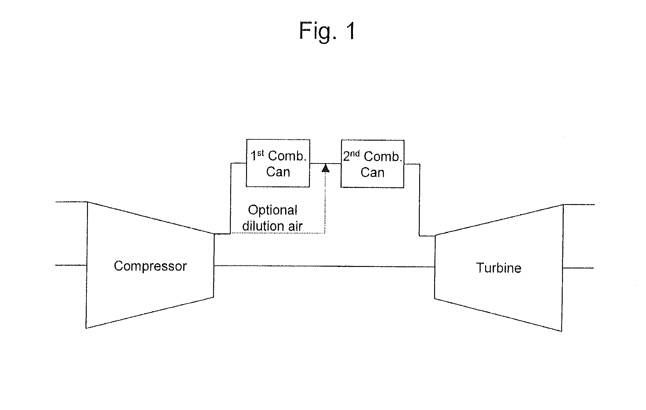
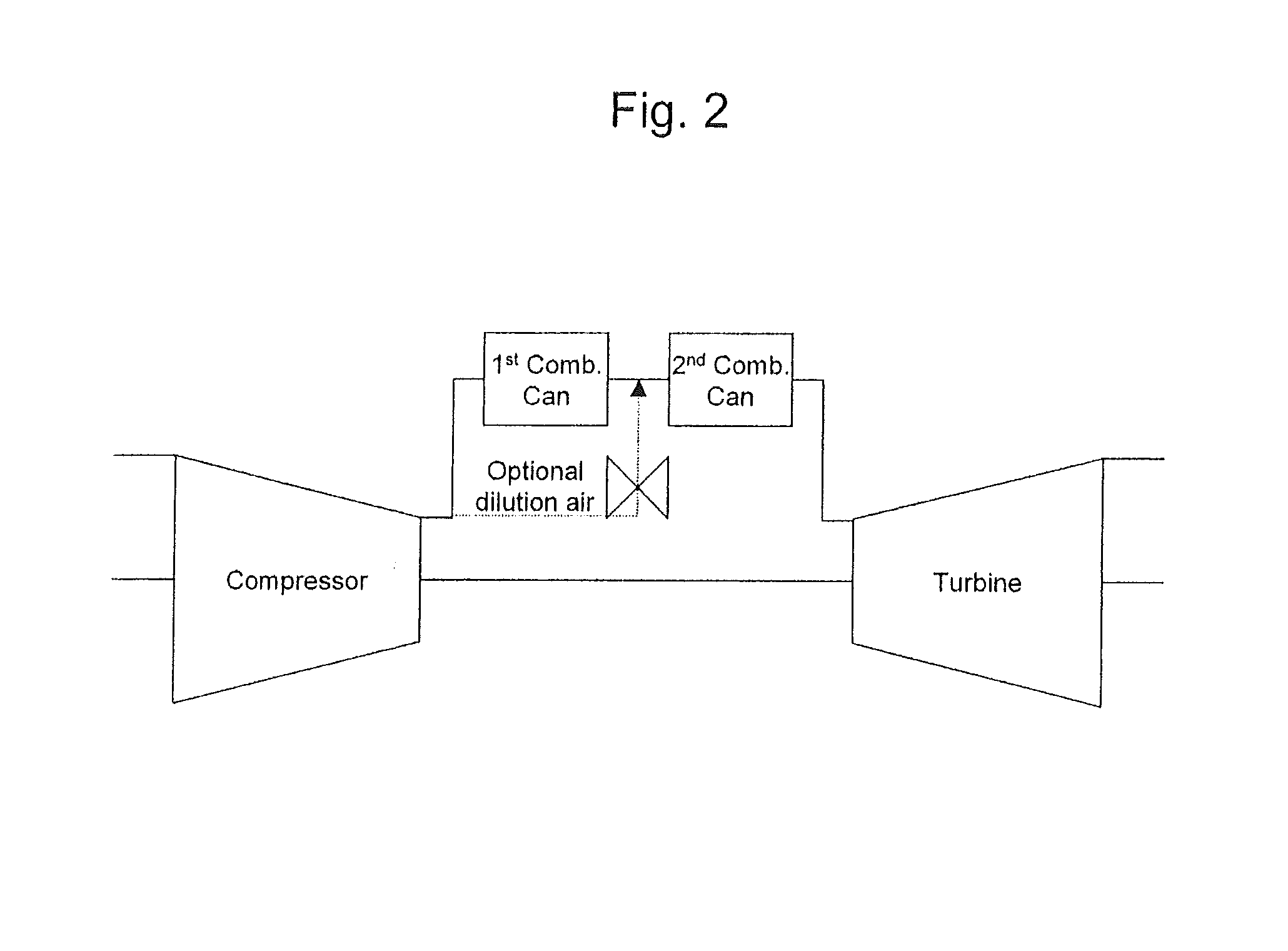
[0060]FIGS. 1 to 3 shows gas turbine with sequential combustion for implementing the method according to the invention. It comprises a compressor, a first combustor can, a second combustor can and a turbine. Typically, it includes a here not shown generator, which at the cold end of the gas turbine, that is to say at the compressor, is coupled to a shaft of the gas turbine.

[0061]FIG. 1 shows a generic gas turbine using sequential combustion in a can-architecture, thereby a valve for modulation of the dilution air is added;

[0062]FIG. 2 shows a generic gas turbine using sequential combustion in a can-architecture, thereby a valve for modulation of the dilution air is added;

[0063]FIG. 3 shows a generic gas turbine using sequential combustion in a can / annular architecture, thereby a valve for modulation of the dilution air is added;

[0064]On top of the engine architecture shown in FIG. 1 and FIG. 2 the concept is expected to work on the engine architectures shown in FIG. 3. Thereby basic...


PUM


Abstract

The invention concerns a method for a part load CO reduction operation and a low-CO emissions operation of a gas turbine with sequential combustion. The gas turbine essentially includes at least one compressor, a first combustor which is connected downstream to the compressor. The hot gases of the first combustor are admitted at least to an intermediate turbine or directly or indirectly to a second combustor. The hot gases of the second combustor are admitted to a further turbine or directly or indirectly to an energy recovery. At least one combustor runs under a caloric combustion path having a can-architecture, and wherein the air ratio (λ) of the combustion at least of the second combustor is kept below a maximum air ratio (λmax).

Description

CROSS-REFERENCE TO RELATED APPLICATIONS[0001]This application claims priority to PCT / EP2013 / 063091 filed Jun. 24, 2013, which claims priority to European application 12174260.5 filed Jun. 29, 2012, both of which are hereby incorporated in their entireties.TECHNICAL FIELD[0002]The invention refers to a method for operating a gas turbine with sequential combustion. The invention refers additionally to a gas turbine for implementing the method for operating a gas turbine with sequential combustion and low CO emissions.BACKGROUND[0003]CO emissions of gas turbine engines need reductions for the sake of saving the environment. Such emissions are known to appear, when there is not sufficient time in the combustion chamber to ensure the CO to CO2 oxidation, and / or this oxidation is locally quenched due to contact with cold regions in the combustor. Since firing temperatures are smaller under part load conditions CO, and the CO to CO2 oxidation gets slower, thus CO emissions usually tend to ...

Claims


Application Information

Patent Timeline
16 Apr 2015
Publication
US20150101341A1
IPC
F23N1/02; F02C6/00; F23C6/04; F02C3/14
CPC
F23N1/02; F02C3/14; F02C6/003; F23C6/042; F05D2220/74; F02C7/228; F02C9/34; Y02E20/16
Inventors
DUSING, MICHAEL; EROGLU, ADNAN