Integrated plasma fuel cell process

Inactive Publication Date: 2006-02-02
HCE
View PDF11 Cites 24 Cited by
  • Summary
  • Abstract
  • Description
  • Claims
  • Application Information

AI Technical Summary

Benefits of technology

[0015] Carbon dioxide emissions from the invention are used in commerce, that is, some combination of selling it, sequestering it from the environment or discharging it as a waste. Carbon dioxide emissions are significantly reduced due to an increase in overall efficiency o

Problems solved by technology

However, producing hydrogen from existing technologies often involves processes that generate more po

Method used


Image

  • Integrated plasma fuel cell process
  • Integrated plasma fuel cell process
  • Integrated plasma fuel cell process

Examples


Example

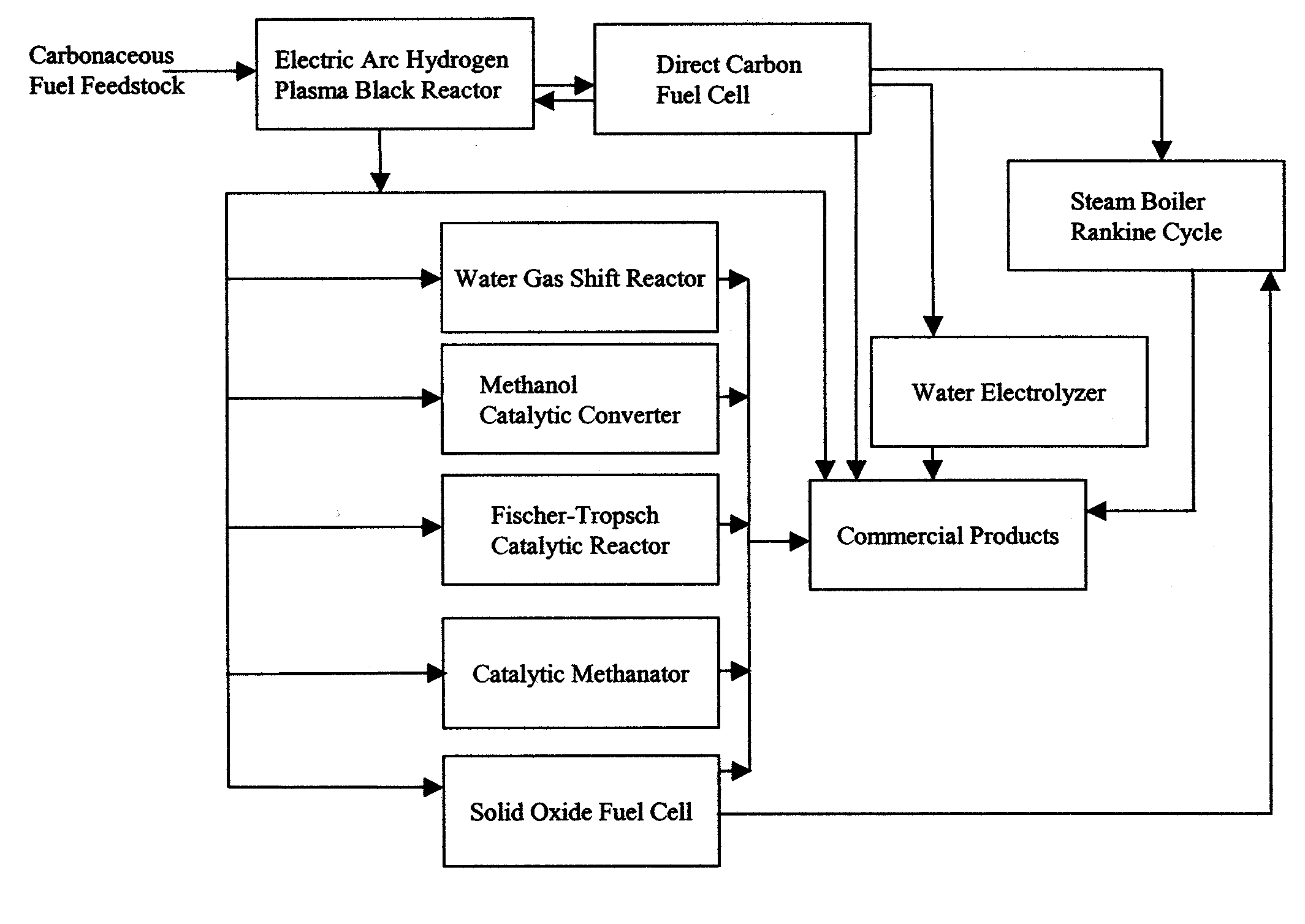
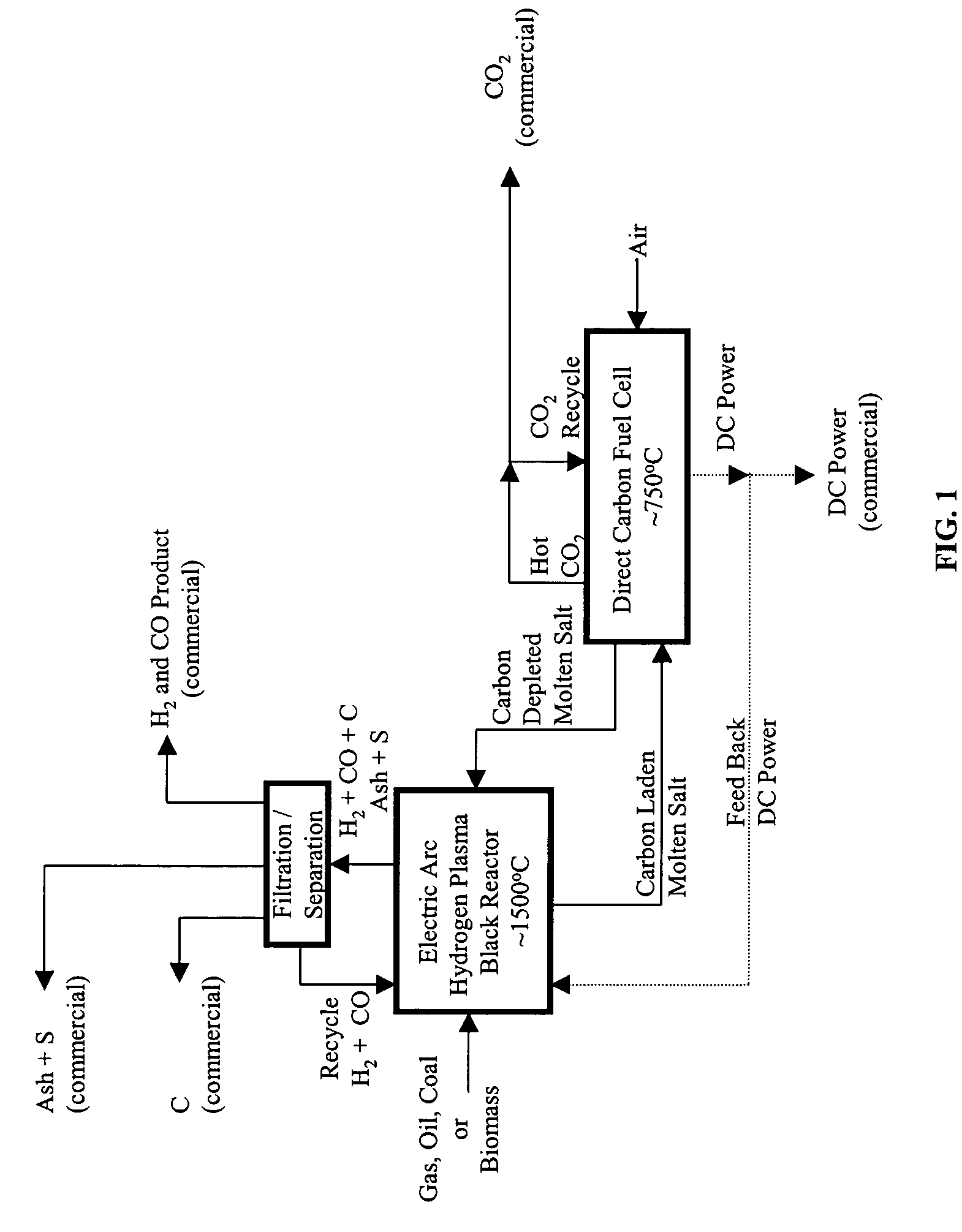
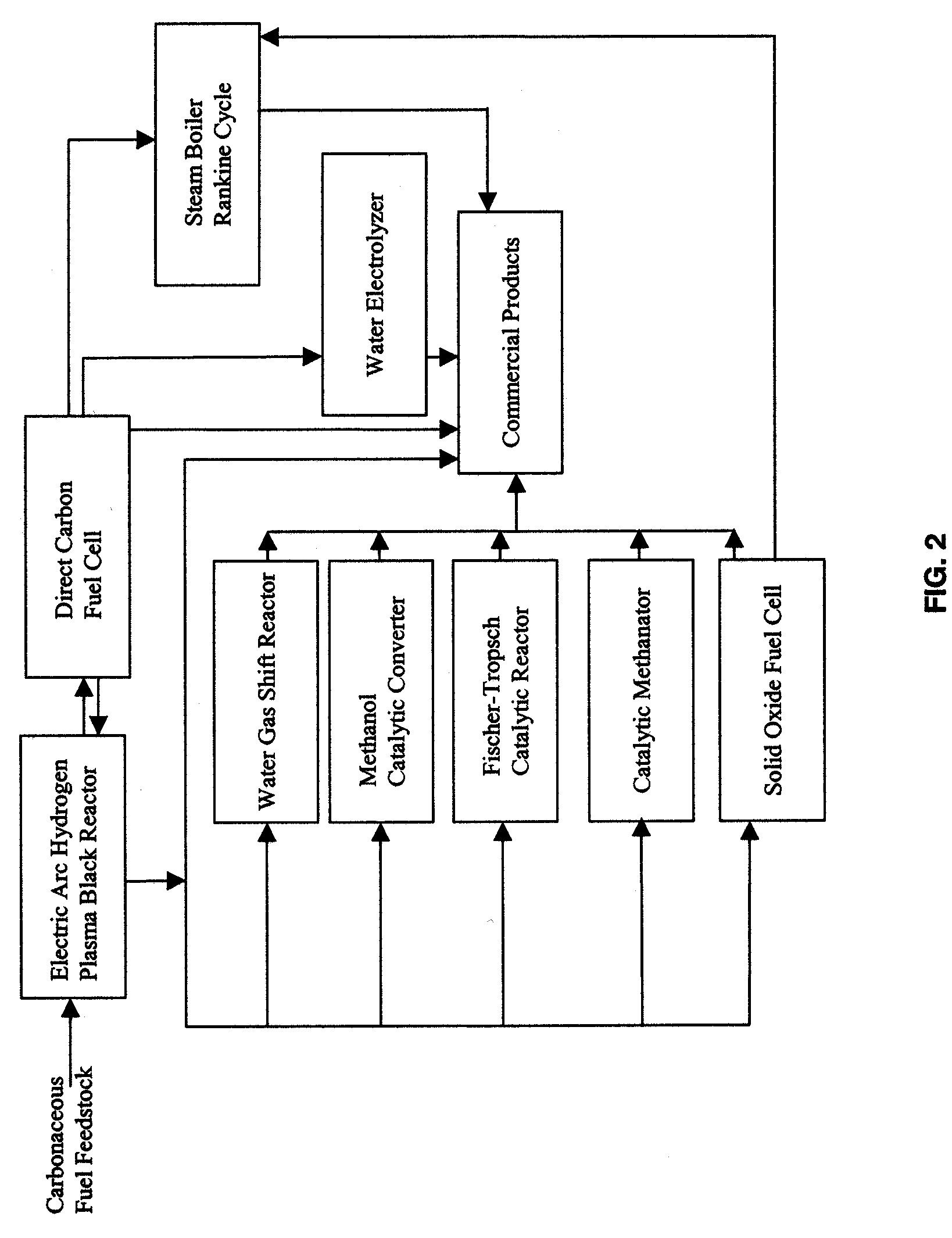
[0019] The method of the invention describes a combined-cycle power, hydrogen and carbon production plant using carbonaceous fuels as feedstock. As used herein, carbonaceous fuels are natural gas, oil, coal and biomass; and, fossil fuels are natural gas, oil, and coal. The combined cycle plant is highly efficient with a potential for very low carbon dioxide emissions.

[0020] The combined cycle plant produces energy products, principally electrical energy, and carbon, carbon monoxide, carbon dioxide, ash, sulfur and hydrogen from fossil or biomass fuels. As shown in FIG. 1, the method claims the integrated use of an Electric Arc Hydrogen Plasma Black Reactor and a molten carbonate Direct Carbon Fuel Cell. The products or outputs of these two components can be used without further processing or can be combined, in alternative embodiments, with one or more other well known equipment to produce steam and electrical energy, liquid and gaseous fuels, and concentrated, that is, high purity...


PUM


Abstract

A method for efficiently producing energy, carbon, carbon monoxide, synthetic carbonaceous liquid and gaseous fuels and hydrogen from fossil or biomass fuels with minimal carbon dioxide emissions.

Description

CROSS REFERENCE TO RELATED APPLICATIONS [0001] This is a Continuation-in-Part (CIP) Application of U.S. application Ser. No. 10 / 604153 filed Jun. 27, 2003, now abandoned. This CIP application claims the benefit of the filing date of patent application Ser. No. 10 / 604153 filed Jun. 27, 2003, now abandoned.BACKGROUND OF INVENTION [0002] This method described herein combines two known technologies to significantly improve the efficiency of energy, carbon, carbon monoxide and hydrogen production starting with a carbon-based feedstock. This higher efficiency produces fewer gaseous and solid pollutants and fewer global warming emissions. [0003] Contributory benefits of the claimed combination arise from claimed subcombinations with other known technologies which greatly enhance the production of hydrogen, oxygen, energy, synthetic carbonaceous gaseous fuels and synthetic carbonaceous liquid fuels. In addition, these subcombinations easily enable the collection of almost all the carbon dio...

Claims


Application Information

Patent Timeline
IPC IPC(8): H01M8/06H01M8/18H01MH01M8/04
CPCY02E60/50Y02E60/528H01M8/04H01M2008/1293H01M8/1246H01M8/10H01M8/0612
Inventor STEINBERG, MEYER
Owner HCE
Why Eureka
Try Eureka