Method for reducing diesel engine emissions, and diesel engine

Active Publication Date: 2010-12-02
VOLVO LASTVAGNAR AB
View PDF9 Cites 11 Cited by
  • Summary
  • Abstract
  • Description
  • Claims
  • Application Information

AI Technical Summary

Benefits of technology

[0005]While operators might connect their vehicles to external or auxiliary power supplies in some circumstances, instead of idling their engines, to do so it is necessary that the vehicle be near an external or auxiliary power supply. These methods inherently reduce emissions but the primary purpose for their implementation is to reduce fuel consumption of the vehicle.
[0006]It is desirable to provide a technique for reducing engine emissions when the engine operates at low loads or idles. As there is no “throttle” in most diesel applications, idle can be considered to be the condition when the engine operates at a load required to overcome friction torque and accessory loading from engine and chassis systems.
[0007]According to an aspect of the present invention, a method for controlling emissions during low-load diesel engine operation is provided, the engine comprising at least one piston movable in a cylinder between a top dead center and a bottom de

Problems solved by technology

Current known emissions control strategies are unable to achieve this target without damage to engine components.
For example, current methods of implementing exhaust gas recirculation (EGR) at idle will tend to cause EGR cooler fouling and engine sludge and varnishing.
Also, during engine idle, there is a danger of after-treatment system damage.
This collection can cause extreme back pressure leading to engine damage or after-treatment damage and, if there is enough hydrocarbon present in the system, when the exhaust gas temperature rises to a sufficiently high level, the unburned fuel can ignite and cause the after-treatment system to melt down or crack, thereby destroying it.
The low thermal state is usu

Method used


Image

  • Method for reducing diesel engine emissions, and diesel engine
  • Method for reducing diesel engine emissions, and diesel engine

Examples


Embodiment Construction

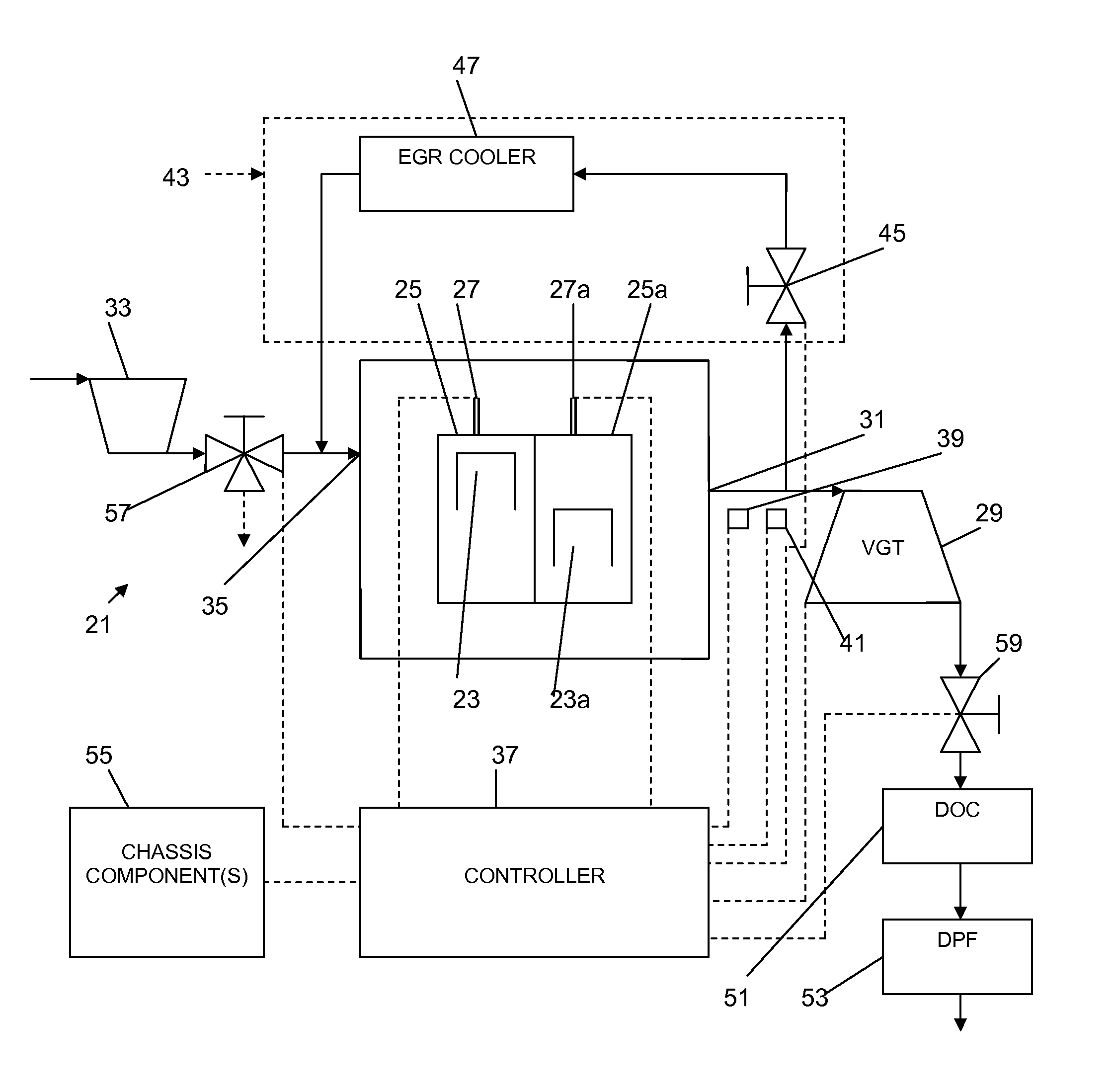
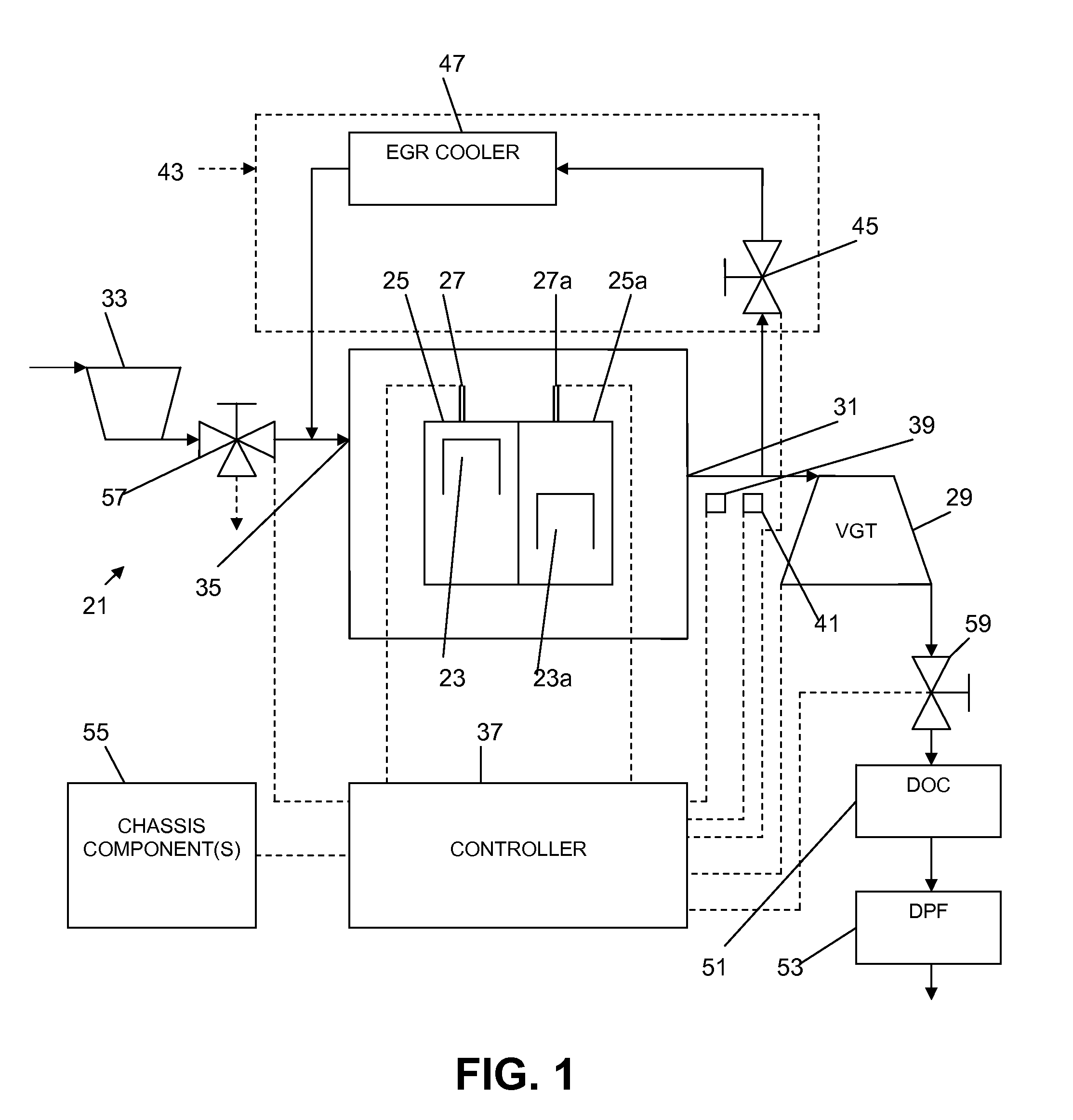
[0011]A diesel engine 21 according to an aspect of the present invention is seen in FIG. 1 and comprises at least one piston 23 movable in a cylinder 25 between a top dead center (TDC) and a bottom dead center (BDC) position. A fuel injector 27 is provided for injecting fuel into the cylinder, ordinarily proximate TDC, and the combination of temperature and pressure causes the fuel to combust and force the piston toward the BDC position. The piston 23 is ordinarily linked to a crankshaft (not shown) that is turned as the piston reciprocates.

[0012]A variable geometry turbine (VGT) 29 is provided downstream of an exhaust 31 of the engine 21 through which exhaust from the cylinder 25 is adapted to flow. The VGT 29 is typically part of a turbocharger arrangement including a compressor 33 that is arranged upstream of the inlet 35 for boosting engine intake air pressure. The VGT 29 has conventional VGT vanes (not shown) for varying the size of an inlet opening of the VGT. The positions of...


PUM


Abstract

A method for controlling emissions during low-load diesel engine operation is provided. The engine includes at least one piston movable in a cylinder between a top dead center and a bottom dead center position, a fuel injector for injecting fuel into the cylinder, and a variable geometry turbine through which exhaust from the engine is adapted to flow. According to the method, the engine is operated at low load, NOx emissions are measured at an exhaust of the engine, and a variable geometry turbine inlet opening size is controlled responsive to NOx emissions measurements so that NOx emission levels are controlled.

Description

BACKGROUND AND SUMMARY[0001]The present invention relates generally to methods and an engine for reduced diesel emissions.[0002]The stringent emissions regulations imposed by United States and European regulatory agencies have progressively reduced the amount of emissions allowed in the exhaust gases of diesel engines. Recent proposals from regulating bodies have mandated that engine manufacturers maintain a maximum NOx emission of 30 g / hr during extended idling conditions.[0003]Current known emissions control strategies are unable to achieve this target without damage to engine components. For example, current methods of implementing exhaust gas recirculation (EGR) at idle will tend to cause EGR cooler fouling and engine sludge and varnishing. Repercussions from this can vary from component replacement to complete engine failure. Also, during engine idle, there is a danger of after-treatment system damage. The cooler exhaust temperatures and higher hydrocarbon environment can cause...

Claims


Application Information

Patent Timeline
IPC IPC(8): F02D23/00F02B33/44F01N3/00
CPCF02B3/06F02B37/24F02D23/02F02D41/0007F02D41/1446Y02T10/144F02D41/1461F02D2250/36F02M25/0707F02M25/0713F02M25/0727F02D41/146F02M26/05F02M26/10F02M26/23Y02T10/12
Inventor GIBBLE, JOHN C.SUDER, TIMOTHY
Owner VOLVO LASTVAGNAR AB
Why Eureka
Try Eureka