Method for operating a self-igniting internal combustion engine and corresponding control device
- Summary
- Abstract
- Description
- Claims
- Application Information
AI Technical Summary
Benefits of technology
Problems solved by technology
Method used
Image
Examples
Embodiment Construction
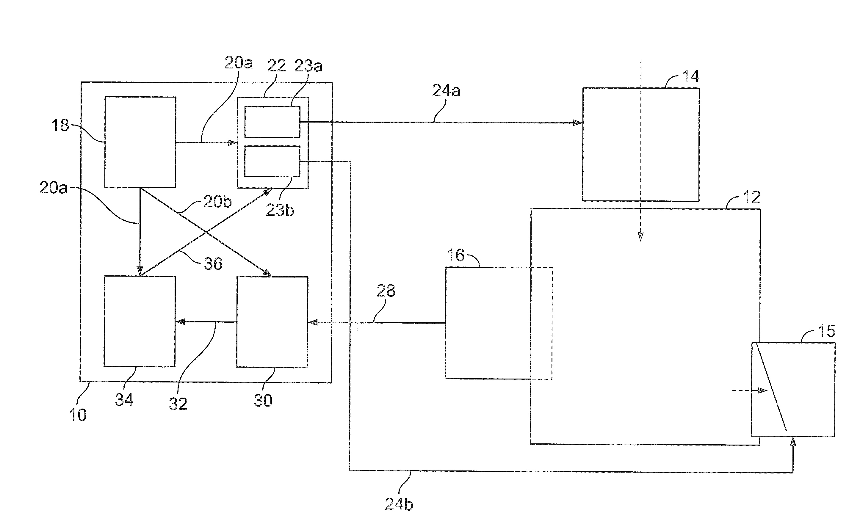
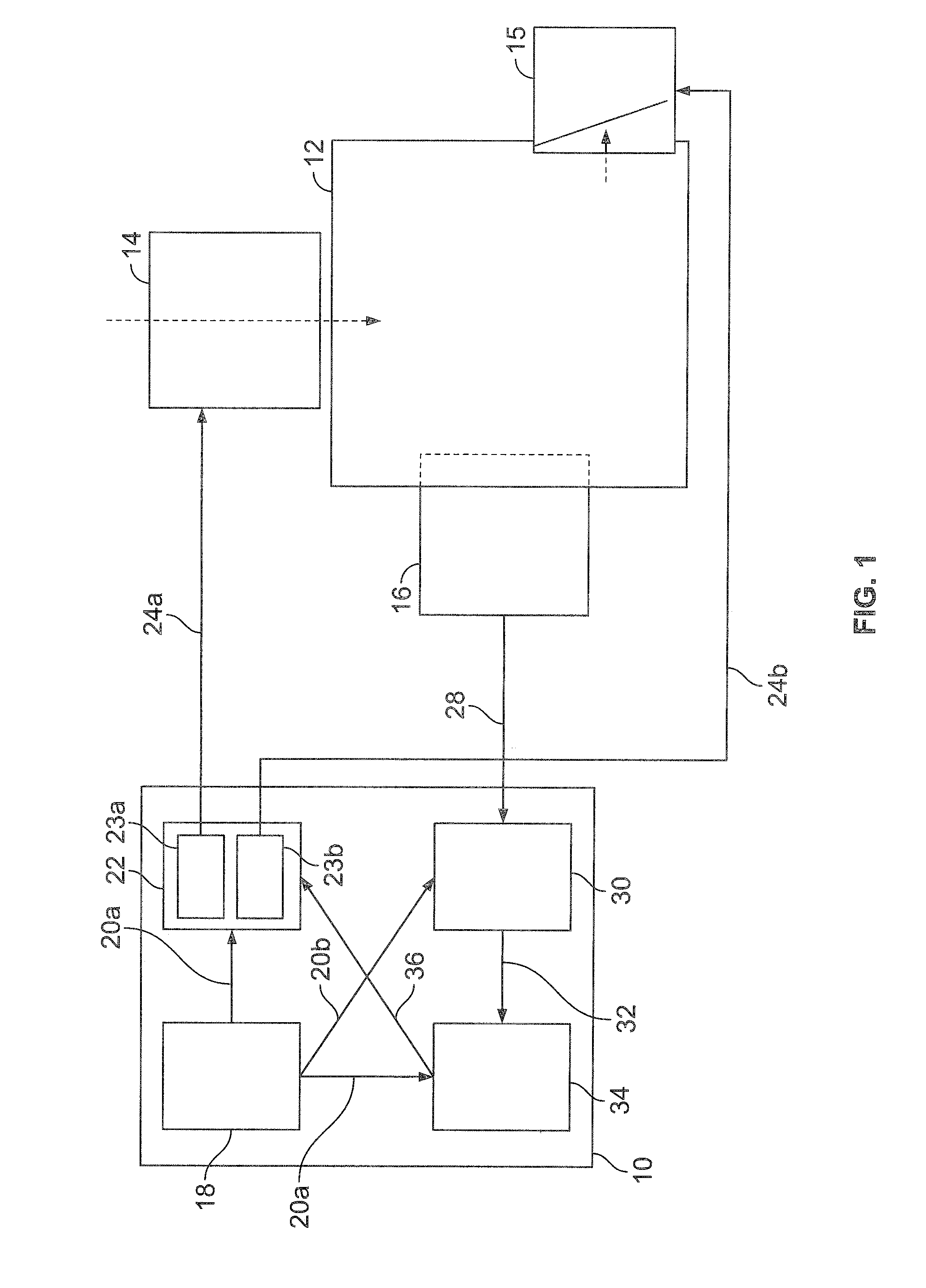
[0054]FIG. 1 is a schematic representation of an embodiment of the control device for operating a self-igniting internal combustion engine. Control device 10 may be mounted close to a self-igniting internal combustion engine 12 having an injector 14, an exhaust gas valve 15 and a cylinder pressure sensor 16. Alternatively, control device 10 may also be a component of a central vehicle control system. In that case, control device 10 is connected to components 14, 15, 16 via signal lines and / or via a vehicle bus.
[0055]Control device 10 includes an output device 18 for providing a comparison value with respect to combustion position, an injector control variable and an exhaust gas valve control variable. In this instance, the comparison value is selected so that it corresponds to a preferred combustion position. The comparison may, for example, be the combustion center MFB50 (mass fraction burnt 50%) or a different crank angle for a specific energy turnover of a combustion.
[0056]The in...
PUM
 Abstract
Description
Claims
Application Information
 - R&D
- Intellectual Property
- Life Sciences
- Materials
- Tech Scout
- Unparalleled Data Quality
- Higher Quality Content
- 60% Fewer Hallucinations
Browse by: Latest US Patents, China's latest patents, Technical Efficacy Thesaurus, Application Domain, Technology Topic, Popular Technical Reports.
© 2025 PatSnap. All rights reserved.Legal|Privacy policy|Modern Slavery Act Transparency Statement|Sitemap|About US| Contact US: help@patsnap.com


