Non-thermal plasma ignition arc suppression

a plasma ignition and suppression technology, applied in the manufacture of spark plugs, engine components, electrical equipment, etc., can solve problems such as reducing the quality of ignition, and achieve the effects of reducing or eliminating arcing, reducing co2 emissions, and improving fuel economy

Active Publication Date: 2012-05-10
FEDERAL MOGUL IGNITION
View PDF3 Cites 28 Cited by
  • Summary
  • Abstract
  • Description
  • Claims
  • Application Information

AI Technical Summary

Benefits of technology

[0010]The igniter of the present invention, including the insulator with electrically conducting elements, reduces or eliminates arcing during operation of the corona ignition system, compared to other igniters without the electrically conducting elements. The igniter creates a controlled and repeatable non-thermal plasma including multiple streams of ions in the form of a corona. The corona discharge emitted from the igniter provides rapid ignition and burning of the fuel mixture, which leads to numerous benefits when used in an internal combustion engine applications, such as improved fuel economy and reduced CO2 emissions.

Problems solved by technology

The arc discharge occupies a much smaller space in the combustion chamber than the corona discharge and thus can reduce the quality of ignition.

Method used


Image

  • Non-thermal plasma ignition arc suppression
  • Non-thermal plasma ignition arc suppression
  • Non-thermal plasma ignition arc suppression

Examples


Embodiment Construction

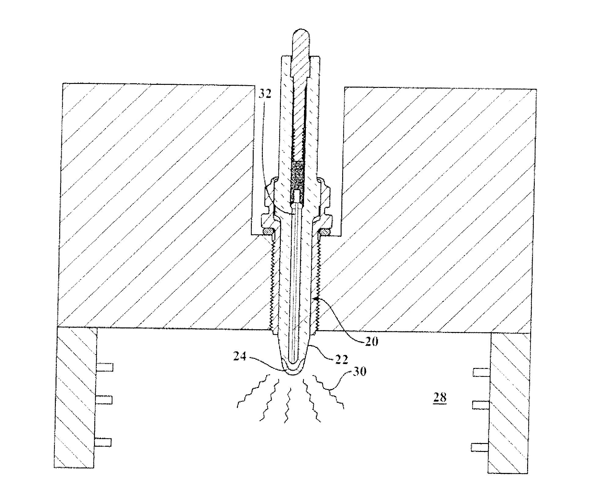
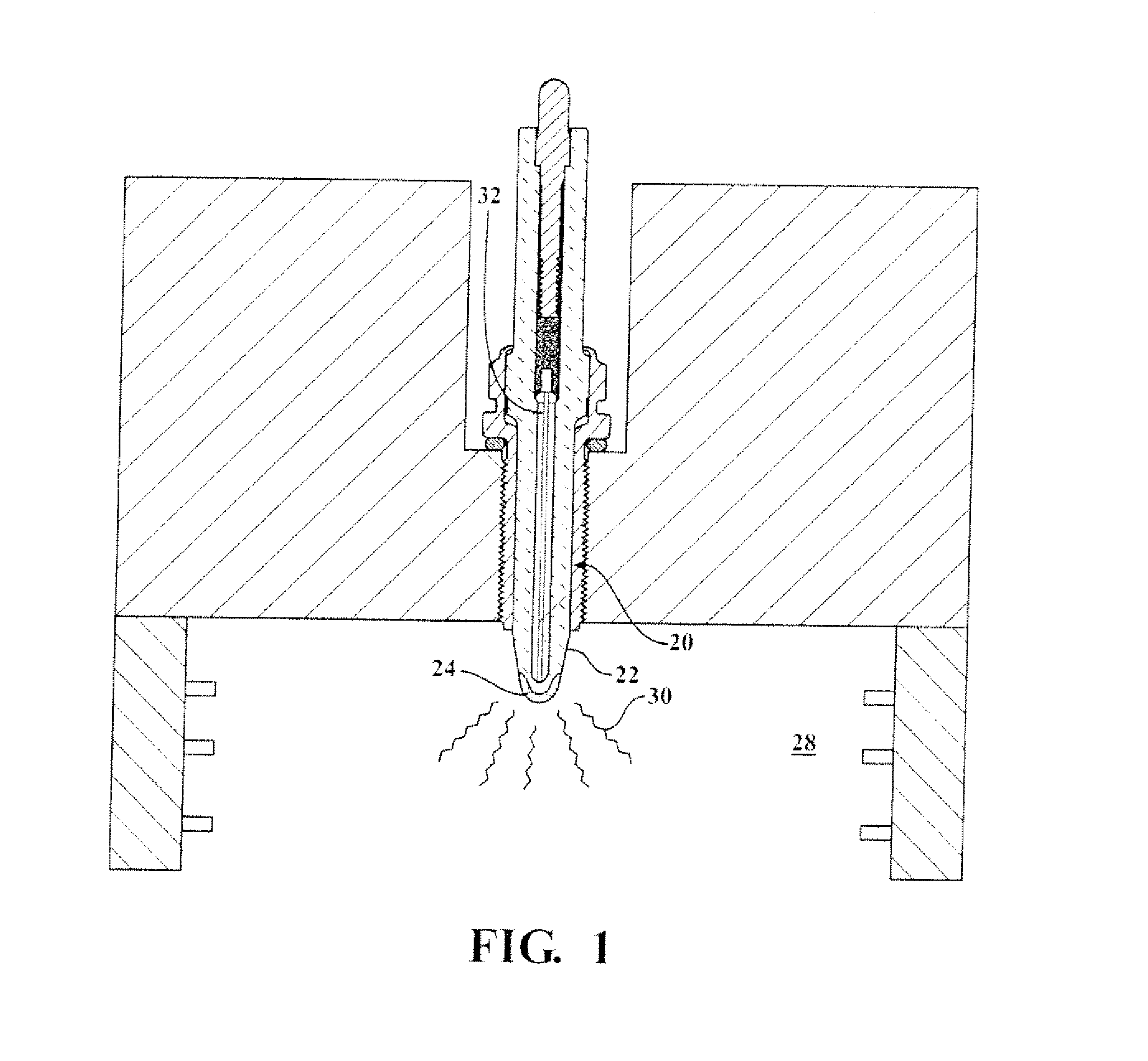
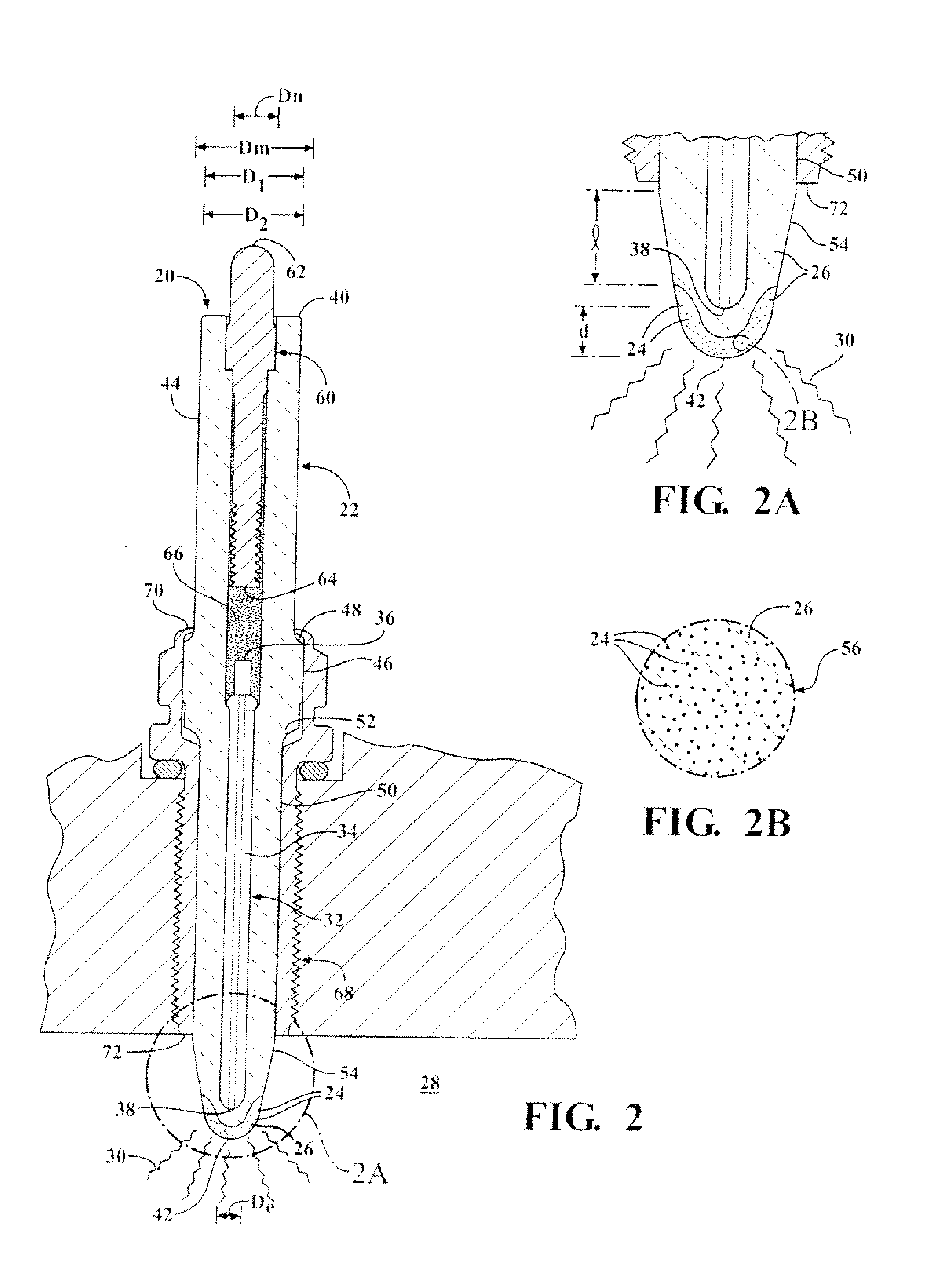
[0019]One aspect of the invention provides an igniter 20 for a corona ignition system, as shown in FIGS. 1-3. The igniter 20 includes an insulator 22 with a plurality of electrically conducting elements 24 disposed in a matrix 26 of electrically insulating material, such as metal particles embedded in the matrix 26, or holes in the matrix 26. As shown in FIG. 1, the igniter 20 is disposed in a combustion chamber 28 of an internal combustion engine and receives a voltage from a power source (not shown). An electrode 32 of the igniter 20 is charged to a high RF voltage potential, creating a strong RF electric field in the combustion chamber. The electric field is controlled so the mixture of fuel and air in the combustion chamber maintains dielectric properties. The electrode 32 emits a non-thermal plasma including multiple streams of ions forming a corona 30 to ionize a portion of the fuel and air in the combustion chamber 28.

[0020]The electrode 32 of the igniter 20 includes an elect...


PUM


Abstract

An igniter (20) of a corona ignition system emits a non-thermal plasma in the form of a corona (30) to ionize and ignite a fuel mixture. The igniter (20) includes an electrode (32) and a ceramic insulator (22) surrounding the electrode (32). The insulator (22) surrounds a firing end (38) of the electrode (32) and blocks the electrode (32) from exposure to the combustion chamber (28). The insulator (22) presents a firing surface (56) exposed to the combustion chamber (28) and emitting the non-thermal plasma. A plurality of electrically conducting elements (24) are disposed in a matrix (26) of the ceramic material and along the firing surface (56) of the insulator (22), such as metal particles embedded in the ceramic material or holes in the ceramic material. The electrically conducting elements (24) reduce arc discharge during operation of the igniter (20) and thus improve the quality of ignition.

Description

CROSS REFERENCE TO RELATED APPLICATION[0001]This application claims the benefit of U.S. provisional application Ser. No. 61 / 407,633, filed Oct. 28, 2010, and U.S. provisional application Ser. No. 61 / 407,643, filed Oct. 28, 2010, which are incorporated herein by reference in their entirety.BACKGROUND OF THE INVENTION[0002]1. Field of the Invention[0003]This invention relates generally to a corona discharge igniter for emitting a non-thermal plasma to ignite a mixture of fuel and air of a combustion chamber, and methods of manufacturing the same.[0004]2. Description of the Prior Art[0005]An example of a corona discharge ignition system is disclosed in U.S. Pat. No. 6,883,507 to Freen. In the corona discharge ignition system, an electrode of an igniter is charged to a high radio frequency (“RF”) voltage potential, creating a strong RF electric field in the combustion chamber. The electric field causes a portion of the fuel-air mixture in the combustion chamber to ionize and begin diele...

Claims


Application Information

Patent Timeline
Patent Type & Authority Applications(United States)
IPC IPC(8): H01T13/20H01T21/02
CPCF02P23/04H01T21/02H01T13/50H01T13/20
Inventor LYKOWSKI, JAMES D.HAMPTON, KEITHWALKER, JR., WILLIAM J.
Owner FEDERAL MOGUL IGNITION
Why Eureka
Try Eureka