Propagation rate measurement device, propagation rate measurement program, and propagation rate measurement method

Active Publication Date: 2015-05-07
FURUNO ELECTRIC CO LTD
View PDF6 Cites 0 Cited by
  • Summary
  • Abstract
  • Description
  • Claims
  • Application Information

AI Technical Summary

Benefits of technology

This patent aims to improve the accuracy and reliability of sonic speed measurement devices while reducing the amount of calculations needed. It does this by integrating certain signals after performing a Fourier transform and correcting them based on the receivers. This integration allows for accurate evaluation of the intensity of the integrated signal.

Problems solved by technology

If data interpolation is performed based on a strict theory such as Fourier interpolation in a time domain, the processing takes a long time.
It is also possible to give priority to shortening the processing time and use a simple interpolation method such as linear function approximation, but in this case there may be a decrease in the accuracy at which sonic speed is derived.
Also, the configuration in Patent Literature 1 involves finding an integrated waveform by integrating the received signals, so if there is a large amount of data in the received signals, more computation will be required for the integration processing, which is a problem in that the calculation may take a long time.
If the calculation takes a long time, the sonic speed cannot be measured smoothly, which puts the operator of this sonic speed measurement device under psychological stress.
Also, since this process does not reflect real time well, finding the best measurement location can be difficult, and it may be impossible to perform accurate sonic speed measurement.

Method used


Image

  • Propagation rate measurement device, propagation rate measurement program, and propagation rate measurement method
  • Propagation rate measurement device, propagation rate measurement program, and propagation rate measurement method
  • Propagation rate measurement device, propagation rate measurement program, and propagation rate measurement method

Examples


Embodiment Construction

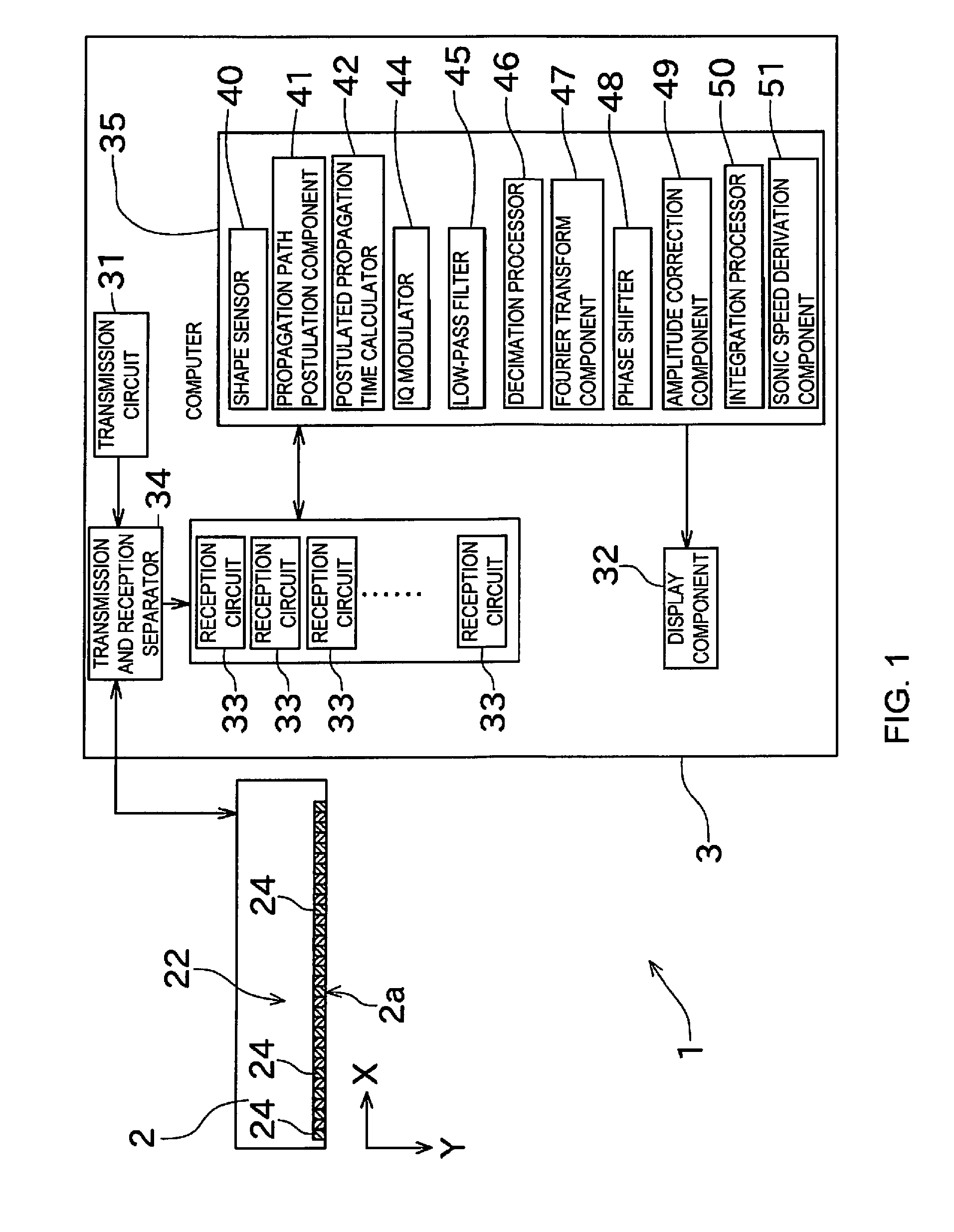
[0031]An embodiment of the present invention will now be described through reference to the drawings. FIG. 1 is a block diagram of an ultrasonic diagnostic device, serving as the propagation rate measurement device pertaining to an embodiment of the present invention.

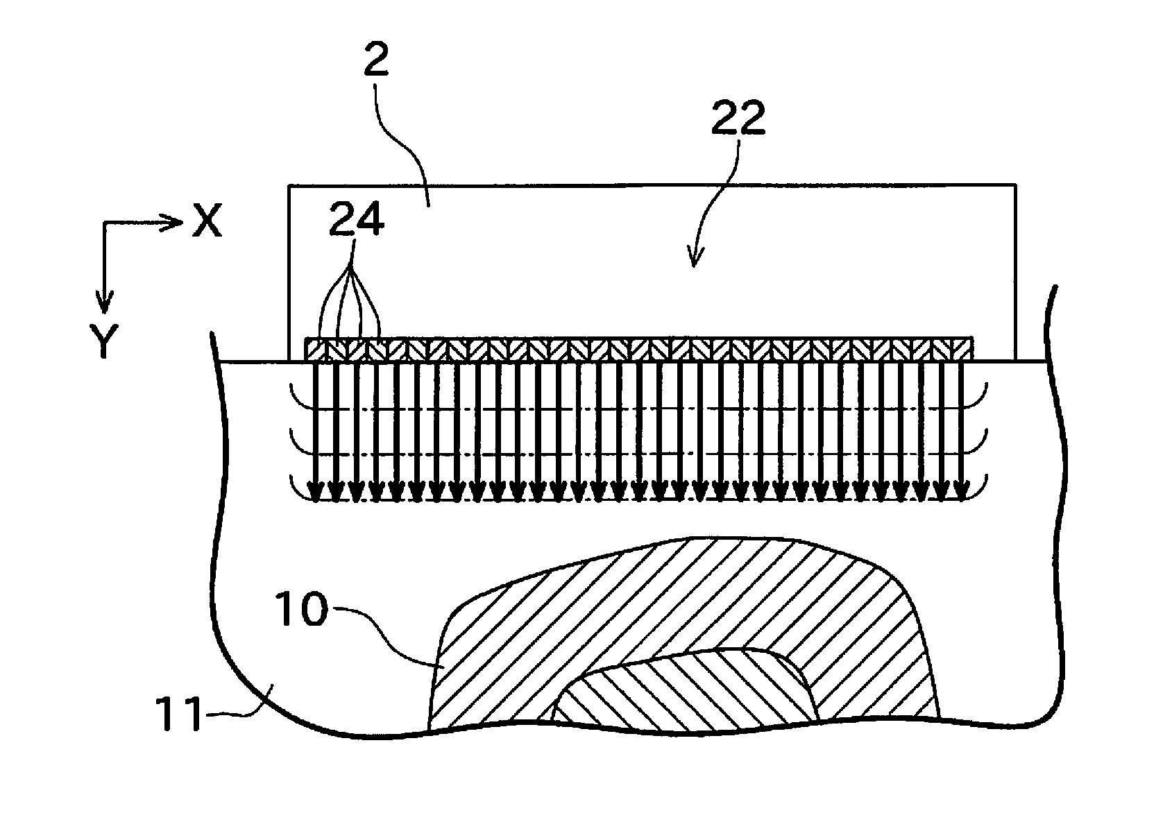
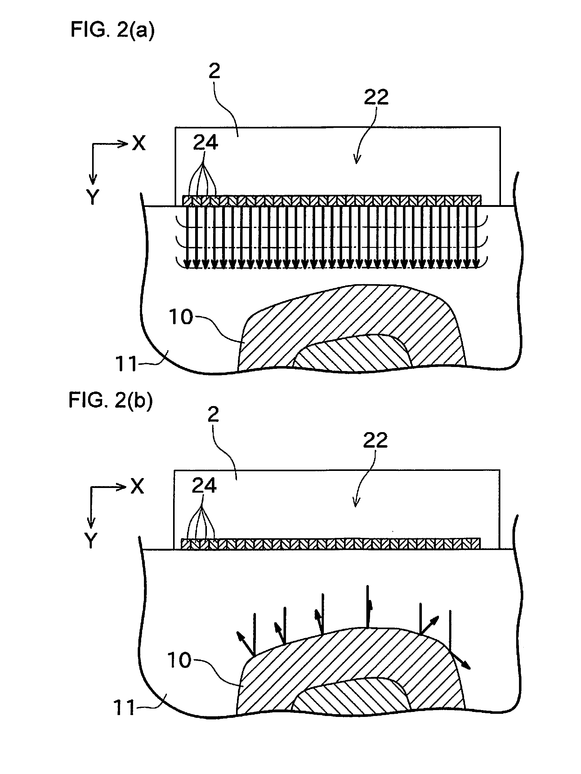
[0032]The ultrasonic diagnostic device 1 in this embodiment is used for diagnosis in human patients, and in particular uses bone as the measurement object. The ultrasonic diagnostic device 1 in this embodiment functions as a sonic speed measurement device for measuring the sonic speed in bone (the propagation rate of an ultrasonic wave signal) based on an ultrasonic wave signal that has returned from bone. The strength of a bone (an index of the health of the bone) can be derived by measuring the sonic speed in the bone.

[0033]As shown in FIG. 1, the ultrasonic diagnostic device 1 is made up of an ultrasonic wave transceiver 2 and a device main body 3.

[0034]The ultrasonic wave transceiver 2 send and receives ultrasonic w...


PUM


Abstract

A sonic speed measurement device in which reliability is enhanced while the amount of calculation is minimized is provided. A propagation path postulation component postulates the sonic speed through bone, and calculates propagation paths up until ultrasonic waves transmitted from a wave transmitter are received by oscillators. A postulated propagation time calculator calculates the propagation time it takes for the ultrasonic waves transmitted from the wave transmitter to be received by the oscillators, based on the propagation paths. A Fourier transform component subjects I signals and Q signals of signals outputted by the oscillators to Fourier transform to generate Fourier transform data. A phase shifter shifts the phase of the Fourier transform data for the oscillators in a frequency region according to the propagation time. A sonic speed derivation component determines the validity of the postulated sonic speed based on the Fourier transform data shifted by the phase shifter.

Description

CROSS REFERENCE TO RELATED APPLICATIONS[0001]This application is a U.S. National stage of International Application No. PCT / JP2013 / 059849 filed on Apr. 1, 2013. This application claims priority to Japanese Patent Application No. 2012-115843 filed on May 21, 2012. The entire disclosure of Japanese Patent Application No. 2012-115843 is hereby incorporated herein by reference.BACKGROUND[0002]1. Field of the Invention[0003]The present invention relates primarily to the configuration of a sonic speed measurement device that uses ultrasonic waves to measure the sonic speed through a measurement object.[0004]2. Background Information[0005]There is a known sonic speed measurement device that transmits an ultrasonic wave signal to a measurement object, receives the ultrasonic wave signal that comes back from the measurement object, and derives the sonic speed through the measurement object based on the received ultrasonic wave signal. This type of sonic speed measurement device is discussed ...

Claims


Application Information

Patent Timeline
IPC IPC(8): G01N29/07
CPCG01N2291/103G01N29/07A61B8/0875A61B8/488G01N29/46G01N2291/02483
Inventor CRETIN, DORIAN
Owner FURUNO ELECTRIC CO LTD
Why Eureka
Try Eureka