
X-ray analysis apparatus, x-ray analysis system, x-ray analysis method, and x-ray analysis program

Active Publication Date: 2014-01-23
RIGAKU CORP
View PDF0 Cites 0 Cited by
  • Summary
  • Abstract
  • Description
  • Claims
  • Application Information

AI Technical Summary

Benefits of technology

The invention is for an X-ray analysis system that can convert X-ray intensity distribution accurately while keeping the overall X-ray intensity and calculating amount low. This system can perform reciprocal conversion and reduce the workload involved in X-ray analysis.

Problems solved by technology

However, usually, one-to-one relationship does not hold between data elements even when the conversion operation is parallel transfer or rotation.
However, these methods do not guarantee preservation of a pixel value and an integral value thereof and are not always appropriately applied to an X-ray diffraction or scattering method in which a position and an integral value of a pixel value are important.
However, in this method, while a pixel value is preserved, there is caused deformation of a high-frequency component of space frequency.
Furthermore, a measurement value by a digital detector is limited to an integer, and sometimes an observation coordinate system does not coincide with an ideal observation coordinate system.
For example, in the case such as the detector being inclined, data expression is treated only by using an integer value, and thus a rounding error to an integer value can be accumulated.
However, in this method, calculation explosion occurs (0[N4]) when precision is to be improved.
Furthermore, while a method by triangular division is known (Non-patent Document 6), the number of divisions needs to be increased for improving precision and a calculation amount becomes huge.

Method used


Image

  • X-ray analysis apparatus, x-ray analysis system, x-ray analysis method, and x-ray analysis program
  • X-ray analysis apparatus, x-ray analysis system, x-ray analysis method, and x-ray analysis program
  • X-ray analysis apparatus, x-ray analysis system, x-ray analysis method, and x-ray analysis program

Examples


Embodiment Construction

[0046]Next, an embodiment of the present invention will be explained with reference to the drawings. For ease of understanding the explanation, in each of the drawings, the same reference numeral is attached to the same constituent and duplicated explanation is omitted.

[0047](Configuration of the X-Ray Analysis Apparatus)

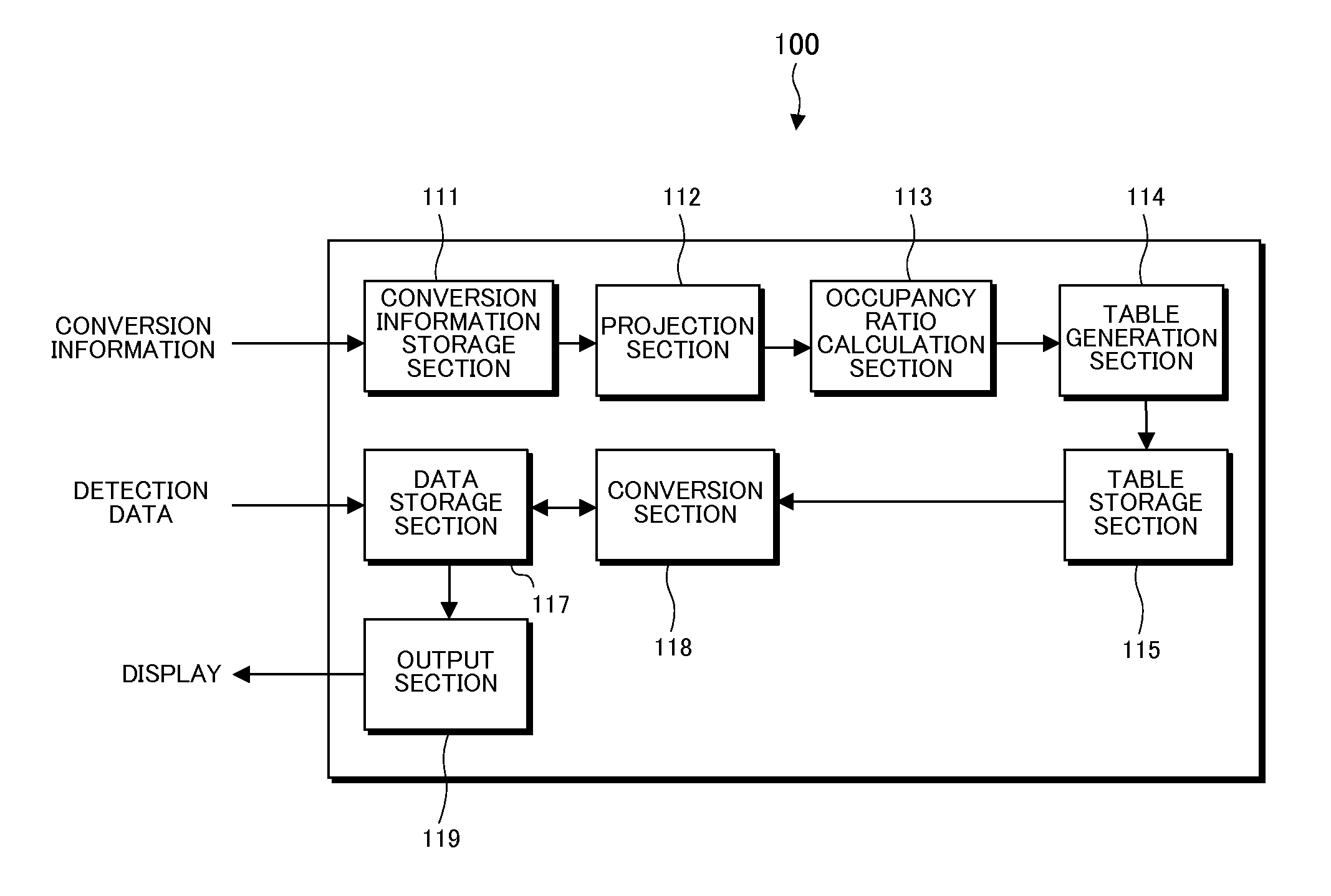
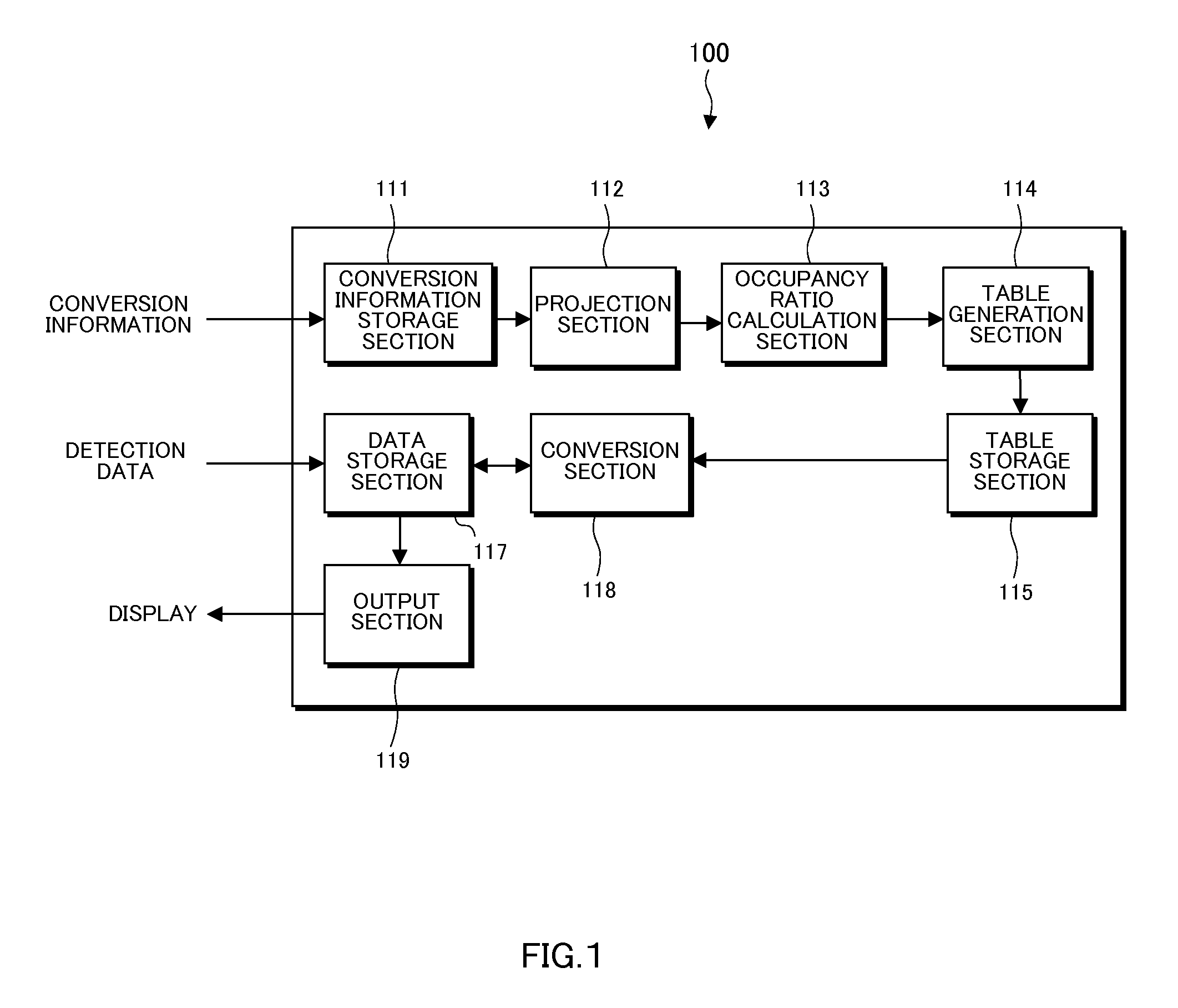
[0048]FIG. 1 is a block diagram showing a configuration of an X-ray analysis apparatus 100. The X-ray analysis apparatus 100 converts an X-ray intensity distribution of discrete data determined for each pixel, from a first plane where the distribution is known into a second plane where the distribution is not known, based on given conversion information such as, for example, a correction value. The pixel is a unit element in a coordinate system of a conversion source or a conversion destination. While a PC can be used as the X-ray analysis apparatus 100, a dedicated machine may also be used. The first plane expresses a plane of the conversion source and the second p...


PUM


Abstract

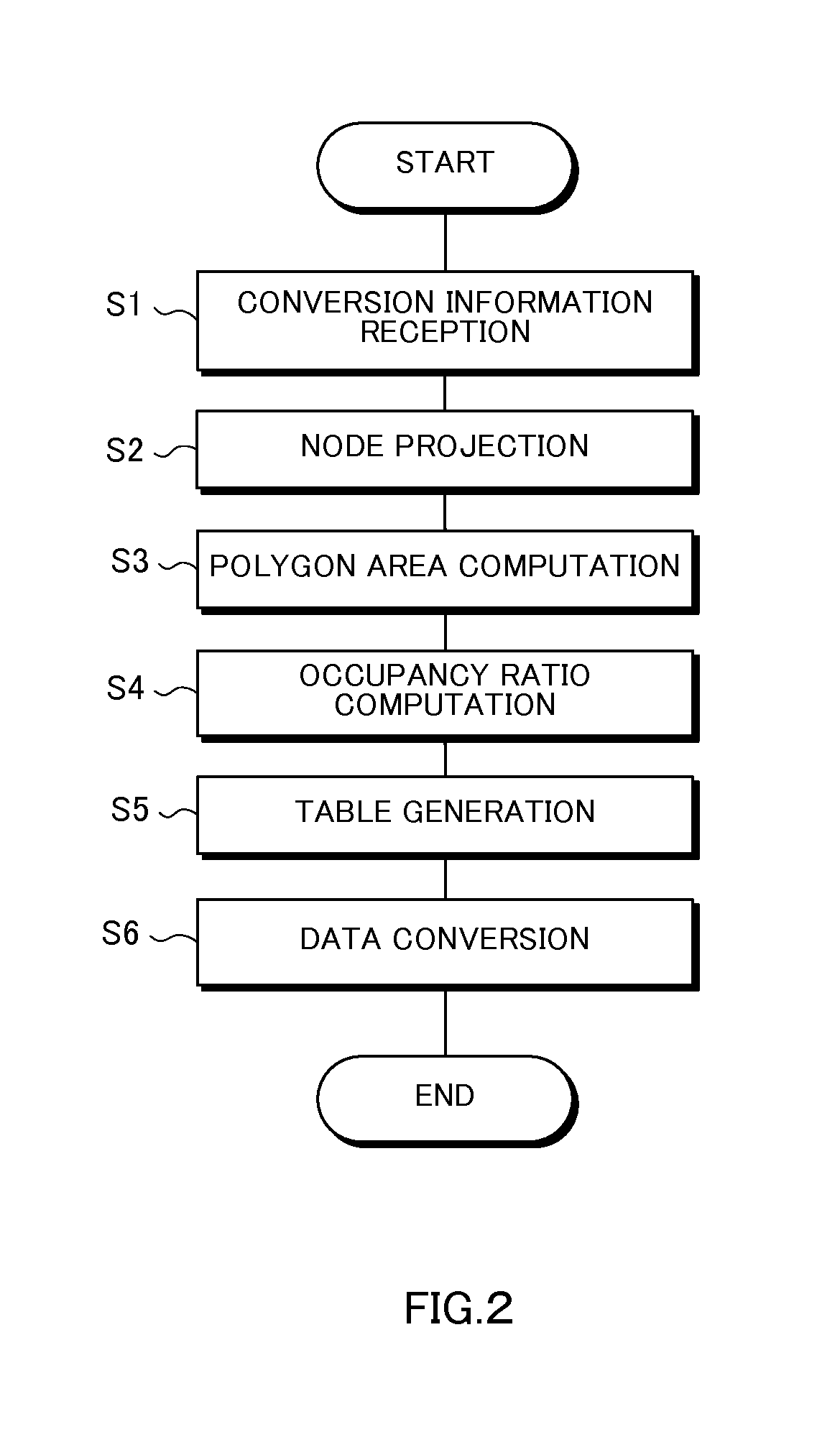
An X-ray analysis apparatus converts an X-ray intensity distribution of discrete data determined for each pixel, from a first plane where the distribution is known into a second plane where the distribution is not known. The X-ray analysis apparatus projects onto the second plane, a grid point which specifies a pixel on the first plane and an intermediate point between the grid points, as nodes, calculates an area of a region where a polygon expressing a projected pixel specified by the projected nodes overlaps with each pixel on the second plane, to thereby calculate an occupancy ratio of the polygon expressing the projected pixel to each pixel on the second plane and distributes X-ray intensity in the pixel on the first plane to the pixel on the second plane based on the occupancy ratio, to thereby convert the X-ray intensity distribution.

Description

BACKGROUND OF THE INVENTION[0001]1. Field of the Invention[0002]The present invention relates to an X-ray analysis apparatus, an X-ray analysis system, an X-ray analysis method, and an X-ray analysis program for converting an X-ray intensity distribution of discrete data determined for each pixel, from a first plane where the distribution is known into a second plane where the distribution is not known.[0003]2. Description of the Related Art[0004]While image data is usually two-dimensional, in consideration of an observation or measurement space, the image data can be regarded as data on a three-dimensional orthogonal coordinate system. Furthermore, data measured by a detector takes a discontinuous value for each pixel and is expressed as spatially discrete information as discrete data.[0005]There is a case where such discrete data on an orthogonal coordinate system needs to be mapped to another coordinate system having the same or a lower dimension. Particularly in mapping in which...

Claims


Application Information

Patent Timeline
IPC IPC(8): G01T1/17
CPCG01T1/17
Inventor ITO, KAZUKIUEJI, YOSHINORIKAJIYOSHI, KOICHINISHI, KUNIO
Owner RIGAKU CORP
Learn More