
Capture-ball-based on-ball point distribution method and motion-posture recognition method, system, and apparatus

Active Publication Date: 2021-11-04
SHENZHEN REALIS MULTIMEDIA TECH CO LTD
View PDF0 Cites 0 Cited by
  • Summary
  • Abstract
  • Description
  • Claims
  • Application Information

AI Technical Summary

Benefits of technology

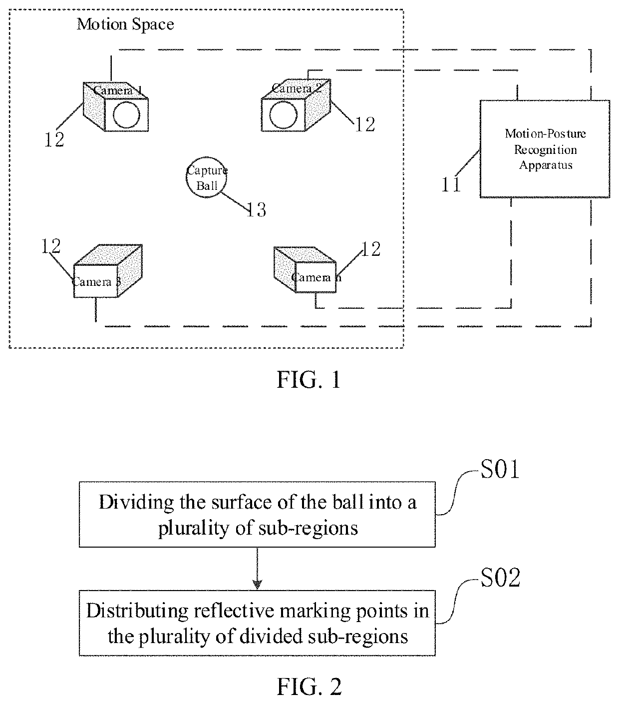
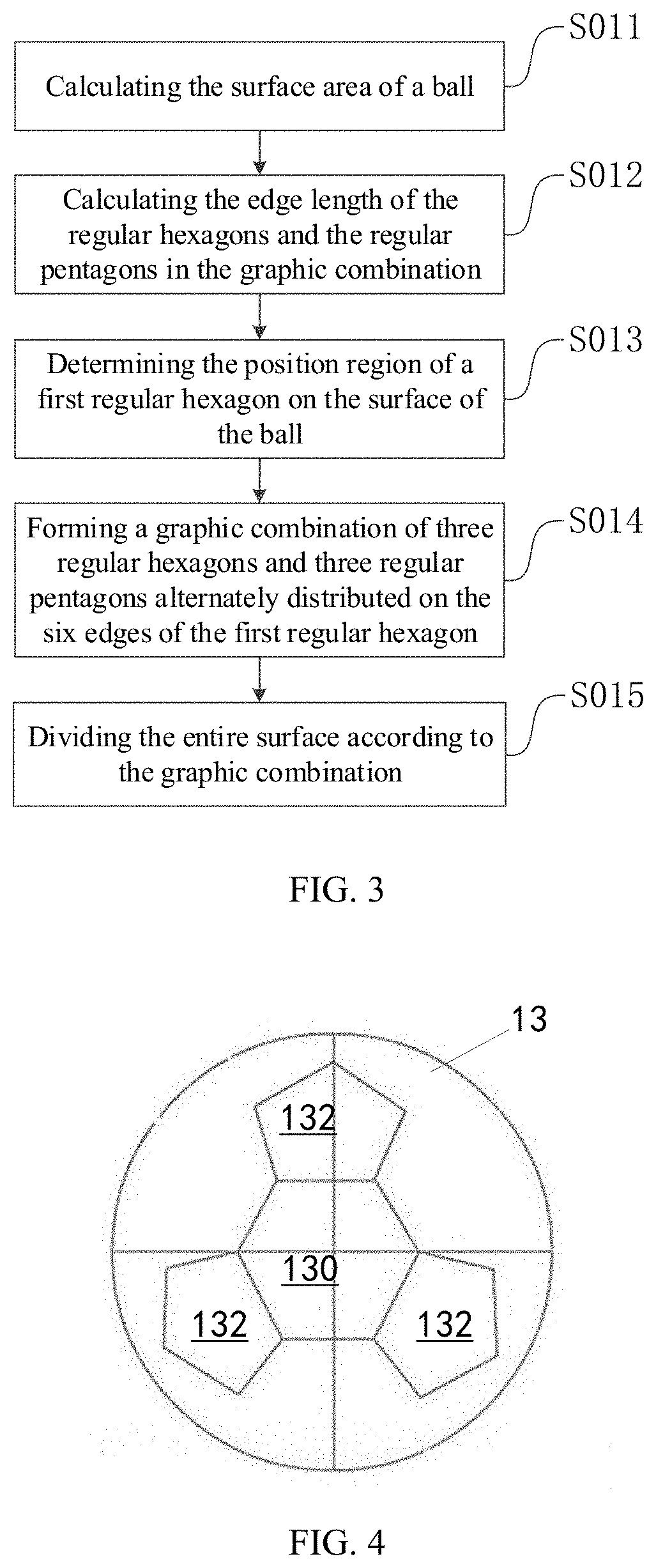
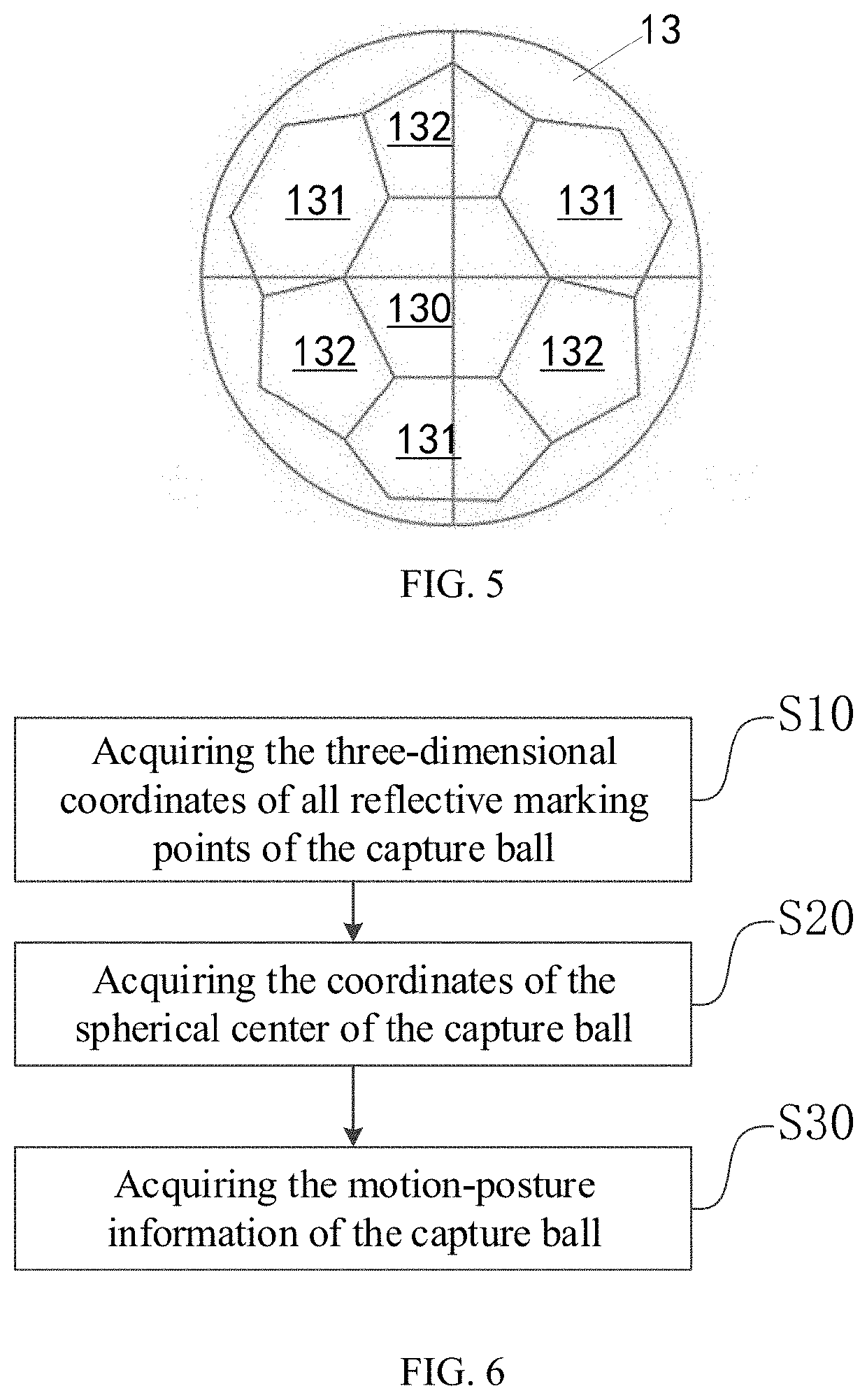
The present invention provides a method and system for improving the recognition and tracking of a capture ball used in optical motion capture. The invention solves the technical problem of how to configure the reflective marking points on the capture ball and how to perform motion-posture recognition on the capture ball. The on-ball point distribution method described in the invention divides the surface of the ball into a uniform geometric distribution state, which facilitates the distribution of reflective marking points. The capture ball obtained using this method has the advantages of uniform point-distribution and small difference in the distances between the reflective marking points, which helps the system quickly identify the reflective marking points and recognize the motion-posture information of the capture ball. The motion-posture recognition method and apparatus described in the invention acquire three-dimensional coordinates of all identifiable reflective marking points and match them to obtain a plurality of matching points on the capture ball, which improves the recognition degree of the capture ball and reduces misidentification. The method also introduces an iterative algorithm for calculating the coordinates of the spherical center, which improves the accuracy of acquiring the motion-posture information of the capture ball and reduces the possibility of misidentification. The invention provides a convenient and efficient solution for real-time posture recognition in practical applications.

Problems solved by technology

However, to capture some target objects whose movement mode is not fixed, such as balls, the method may not work.
Because the capture objects have random motion in all directions in space, the direction of motion cannot be controlled, and each part may possibly collide with the contact surface, causing damages to the rigid body.
First, when a capture ball is recognized in the rigid body manner, since a lot of reflective stickers are distributed on the capture ball to configure a large number of reflective markers, in order to comprehensively recognize the motion posture of the capture ball, in a later process of posture recognition and trajectory tracking, it is required to traverse the three-dimensional coordinates of each reflective marker, and thus the amount of calculation is tremendous, which may greatly affect the effect of real-time motion-posture recognition and trajectory tracking of the capture ball.
Second, the self-structure of the capture ball has a difference in size. A ball with a relatively large diameter will cause unpredictable blocking of the reflective sticker during the movement process, thereby affecting the capturing process and resulting in poor motion-posture recognition.

Method used


Image

  • Capture-ball-based on-ball point distribution method and motion-posture recognition method, system, and apparatus
  • Capture-ball-based on-ball point distribution method and motion-posture recognition method, system, and apparatus
  • Capture-ball-based on-ball point distribution method and motion-posture recognition method, system, and apparatus

Examples


Embodiment Construction

[0033]The present invention will be further described in detail below with reference to the accompanying drawings. Similar elements in different embodiments adopt the numbers for related similar elements. In the following embodiments, many of the details are described in order to provide a better understanding of the application. However, those skilled in the art can easily understand that some of the features may be omitted in different situations, or may be replaced by other elements, materials, and methods. In some cases, some operations related to the present application are not shown or described in the specification. This is to avoid the core part of the present application being overwhelmed by excessive description. For those skilled in the art, detailed description of these related operations is not necessary, and they can fully understand the relevant operations according to the description in the specification and the general technical knowledge in the field.

[0034]In addit...


PUM


Abstract

The present invention provides a capture-ball-based on-ball point distribution method, and a motion-posture recognition method, system, and apparatus. Because the on-ball point distribution method adopts a predetermined graphic combination to divide the surface of the ball, the surface of the ball demonstrates a uniform geometric distribution state, which is conducive to uniformly disposing reflective marking points to form a capture ball that can be used for optical capture, and helps the optical motion capture system recognize the motion-posture information of the capture ball according to the displacement changes of the reflective marking points. In addition, because the motion-posture recognition method adds a method for matching the recognizable reflective marking points and the capture ball in the process of acquiring the plurality of matching points on the capture ball, and introduces an iterative algorithm for calculating the coordinates of the spherical center in the process of acquiring the coordinates of the spherical center of the capture ball, misrecognition caused by matching errors of the reflective marking points and increased coordinate errors of the spherical center can be effectively avoided, conducive to improving the recognition degree of the capture ball in the system.

Description

FIELD OF THE INVENTION[0001]The present invention relates to the field of optical motion capture technology and, more particularly, relates to a capture-ball-based on-ball point distribution method, and a motion-posture recognition method, system, and apparatus.BACKGROUND[0002]In current optical motion capture systems, the motion-posture recognition and trajectory tracking for a target object is typically implemented by capturing the motion trajectories of reflective markers (referring to markers with the surfaces covered by special reflective materials, having common shapes including spherical shapes, hemispherical shapes, etc., and often used for capturing moving objects). Usually, a plurality of reflective markers configured on a capture object is combined into a rigid body that can be captured (here, the rigid body refers to an object that, when moving and after being subjected to a force, the shape and the size are unchanged and the relative positions of the internal points are...

Claims


Application Information

Patent Timeline
IPC IPC(8): G06T7/215G06T7/292G06K9/00G06T7/246G06T7/73
CPCG06T7/215G06T7/292G06T2200/04G06T7/248G06T7/74G06K9/00335G06T2207/10016G06T2207/30204G06T2207/30224G06T2207/10048G06V40/20
Inventor WANG, YUEXU, QIUZI
Owner SHENZHEN REALIS MULTIMEDIA TECH CO LTD
Learn More