Ultra-wide band measurement bridge

Active Publication Date: 2015-05-14
ROHDE & SCHWARZ GMBH & CO KG
View PDF9 Cites 1 Cited by
  • Summary
  • Abstract
  • Description
  • Claims
  • Application Information

AI Technical Summary

Benefits of technology

[0014]A further advantage is achieved, in accordance with another embodiment, if the balun comprises a second portion, wherein the second portion provides a coaxial line of which the inner conductor is connected to the first signal line and of which the outer conductor is connected at a first end of the coaxial line to the second signal line, and wherein at least one first ferrite surrounds the coaxial line. The use of such a ferrite which surrounds the coaxial line means that the balun also suppresses the common-mode component reliably even at very low frequencies.
[0015]In yet another embodiment, an advantage is achieved with the balun if the thin-film resistor layer provides a DGS structure (Defective Ground Structure) in the first portion, so that the thin-film resistor layer is split into two mutually separate thin-film resistor layers, wherein the width of the DGS structure should be optimised corresponding to the substrate material used, and wherein the latter is embodied directly between the two signal lines on the lower side of the substrate. Such a DGS structure has the advantage that the odd-mode signal is still attenuated considerably less strongly than the common-mode signal, so that the common-mode suppression of the balun is increased.
[0016]In one embodiment, further advantage of the balun

Problems solved by technology

It is disadvantageous that, as a result of the different component groups which are used for different frequencies,

Method used


Image

  • Ultra-wide band measurement bridge
  • Ultra-wide band measurement bridge
  • Ultra-wide band measurement bridge

Examples


Example

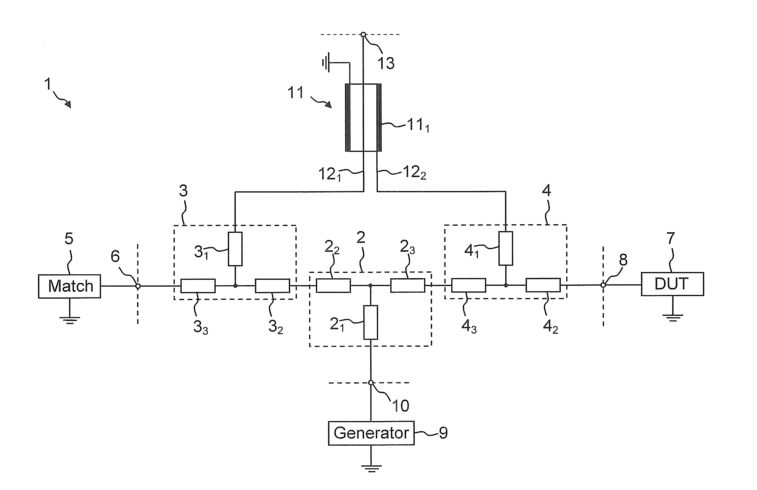
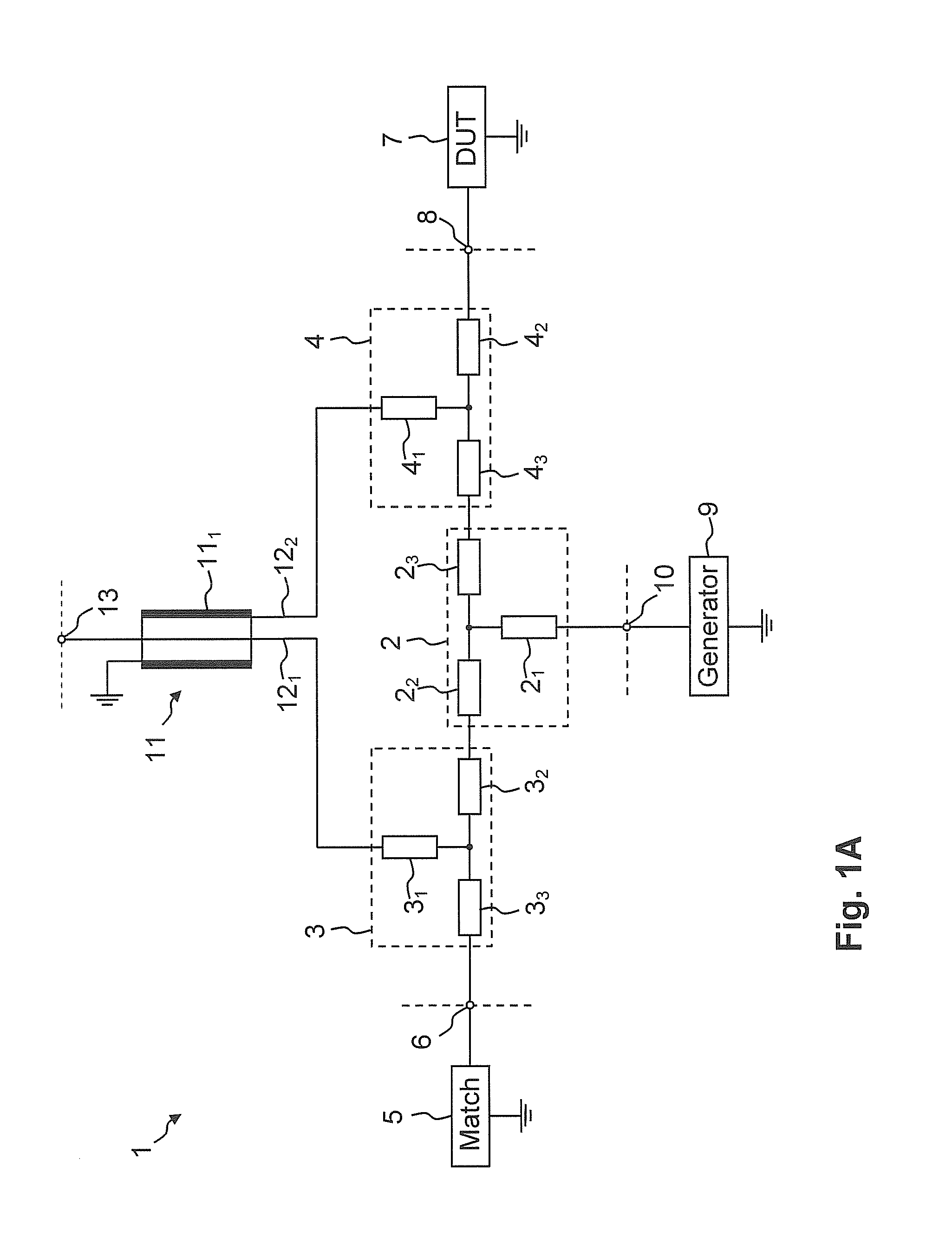
[0035]FIG. 1A shows an exemplary embodiment of an equivalent circuit diagram of the measuring bridge 1. The measuring bridge 1 provides a first matching pad 2, a second matching pad 3 and a third matching pad 4. The first matching pad 2 comprises at least three resistors 21, 22, 23, which are arranged in a T-structure. The second matching pad 3 also comprises at least three resistors 31, 32, 33, which are also arranged in a T-structure. The same applies for the third matching pad 4 which also comprises at least three resistors 41, 42, 43 which are arranged in a T-structure. In this context, the second resistor 22 of the first matching pad 2 is connected to the second resistor 32 of the second matching pad 3. The third resistor 23 of the first matching pad 2 is connected to the third resistor 43 of the third matching pad 4.

[0036]The third resistor 33 of the second matching pad 3 is connected to a calibration standard 5. This calibration standard 5 may be embodied either directly with...


PUM


Abstract

A measuring bridge (1) provides a first matching pad (2), a second matching pad (3) and a third matching pad (4), wherein all matching pads (2, 3, 4) comprise at least three resistors (21, 22, 23, 31, 32, 33, 41, 42, 43) which are arranged in a T-structure. A second resistor (32) of the second matching pad (3) is connected to a second resistor (22) of the first matching pad (2), and a third resistor (43) of the third matching pad (4) is connected to a third resistor (23) of the first matching pad (2). A second resistor (42) of the third matching pad (4) can be connected to a device under test (7). A third resistor (33) of the second matching pad (3) can be connected to a calibration standard (5), and a first resistor (31, 41) of the second and the third matching pad (3, 4) are connected in each case to a signal input of an element (11) which suppresses a common-mode component on its two signal inputs.

Description

CROSS-REFERENCE TO RELATED APPLICATION[0001]The present application is a national phase application of PCT Application No. PCT / EP2013 / 059260, filed May 3, 2013, and claims priority to German Application No. DE 10 2012 207 341.8, filed on May 3, 2012, the entire contents of which are herein incorporated by reference.BACKGROUND OF THE INVENTION[0002]1. Field of the Invention[0003]The invention, according to the various embodiments described herein, relates to a measuring bridge which can be used, for example, in a network analyser in order to supply an excitation signal to a device under test and at the same time to supply reflections of the device under test to an electronic measuring device, and a balun which can be inserted into the measuring bridge, wherein the measuring bridge provides a very high bandwidth.[0004]2. Discussion of the Background[0005]In addition to investigating reflections of a device under test, a measuring bridge can also be used to investigate the transmission...

Claims


Application Information

Patent Timeline
IPC IPC(8): G01R27/06H03H7/42G01R27/28
CPCG01R27/06H03H7/42G01R27/28G01R27/04G01R27/32H01P5/12H01P5/20
Inventor STERNS, MICHAELLEIBFRITZ, MARTIN
Owner ROHDE & SCHWARZ GMBH & CO KG
Why Eureka
Try Eureka