Minimal glove capable of direct and removable adherence to a palm
Inactive Publication Date: 2015-05-21
RODRIGUEZ JANICE
2 Cites 0 Cited by
AI-Extracted Technical Summary
Problems solved by technology
Prolonged coverage of the hand causes uncomfortable situation as most gloves prevent air flow, causing excessive sweating, odor and unsanitary conditions.
However, two problems remain, i.e., the back of hand of a wearer of the glove is typically fully or partially covered.
By having conventional glove portions, albeit small, the benefits of having a minimal glove is not fully realized.
However, the glove covers a substantial portion of a hand, thereby not providing the benefi...
Benefits of technology
[0010]The present invention is directed toward a minimal glove capable of being removably secured to a human palm directly. The minimal glove comprises a flexible sheet having a substrate layer, a backing layer having a top surface and a bottom surface and an attachment layer, wherein the flexible sheet is formed substantially in the shape of a human palm, the substrate layer is disposed on the top surface...
Abstract
A minimal glove capable of being removably secured to a palm directly, the minimal glove comprises a flexible sheet having a substrate layer, a backing layer having a top surface and a bottom surface and an attachment layer, wherein the flexible sheet is formed substantially in the shape of a human palm, the substrate layer is disposed on the top surface of the backing layer and the attachment layer is disposed on the bottom surface of the backing layer and the attachment layer is configured to be removably attached to the palm directly. The minimal glove further comprises a protective sheet on which the attachment layer is attached such that the attachment layer of the flexible sheet is protected from contamination when the protective sheet is not in use.
Application Domain
Garment special featuresGloves +3
Technology Topic
Electrical and Electronics engineering
Image
Examples
- Experimental program(1)
Example
PARTS LIST
[0026] 2—glove [0027] 4—substrate layer [0028] 6—backing layer [0029] 8—attachment layer [0030] 10—hand [0031] 12—palm [0032] 14—finger edge [0033] 16—thumb edge [0034] 18—wrist edge [0035] 20—dorsal edge [0036] 22—hypothenar edge [0037] 24—steering wheel [0038] 26—thickness of glove [0039] 28—finger area [0040] 30—thumb area [0041] 32—wrist area [0042] 34—dorsal area [0043] 36—hypothenar area [0044] 38—skin of palm [0045] 40—crease [0046] 42—cushion patch [0047] 44—aperture [0048] 46—protective sheet [0049] 48—indicium
PARTICULAR ADVANTAGES OF THE INVENTION
[0050]The present glove requires relatively few steps to construct compared to a conventional full or fingerless glove as fabric/leather-type gloves are made of multiple fabric materials that are stitched or glued together creating multiple seams or joints.
[0051]The present glove can be worn year round and in all temperatures or even under a conventional glove if so desired. It also serves as a barrier to transmission of germs to the palm area. In one embodiment, a present glove is disposable as it can be mass produced and produced at low cost. A user of the glove does not need to feel compelled to keep the glove if the glove no longer retains its adhesion properties or when it becomes worn out or contaminated with dirt or germs, e.g., those received at public venues.
[0052]In contrast to conventional full gloves, the present palm glove provides targeted protection, i.e., protection that is afforded for the part of a human body desired to be protected. In this case, the desired part to be protected is the palm of a human hand. In contrast to Nee, in order to dispose a functioning portion, i.e., palm patch (14 of Nee) at the palm of a hand, the palm patch is secured to a hand using finger holes (36, 44, 46 of Nee) and tabs (37, 39, 50, 52 of Nee).
[0053]The protection of a palm is provided without negative effects of a full glove. When worn over an extended period of time, especially at room or elevated temperature, a full glove can cause excessive perspiration as it traps moisture, even with sweat absorbing or wicking materials, making for uncomfortable and unsanitary conditions for its wearer. It is well known that the palm of a hand can experience sweating just as most parts of the rest of a human body. The Applicant discovered that sweating affects the effectiveness of the present attachment pad little in securing the pad to a palm. Another negative effect of a full glove involves wrinkling or bunching of a glove causing significant problems in the dexterity of the hand as allowed by the glove. Without having a conventional full or fingerless glove, bunching problems do not exist in the present glove. Paragraph [0005] of U.S. Pat. Pub. No. 2009/0077714 of Baacke demonstrates such concerns as follows:
[0054]“However, regardless of the particular material utilized to form a glove, oftentimes the glove does not adequately conform to the shape of the hand of the wearer for various reasons, such as the material or materials forming the glove, or the shape of the glove or the shape of the hand of the wearer, among others. In these situations where the glove does not conform to the hand of the wearer, as shown in FIG. 4, when the glove 10′ is flexed by the movement of a hand therein, the material forming the glove will create wrinkles 14′ or bunch, particularly across the palm 12′ of the glove, causing significant problems with regard to the ability of the individual to grasp or hold objects while wearing the glove 10′. In addition, this bunching 14′ will cause premature and uneven wear of certain parts of the glove 10′, namely those portions 16′ that are urged outwardly due the bunching of the glove material, thereby lessening the effective life of the glove 10.”
DETAILED DESCRIPTION OF A PREFERRED EMBODIMENT
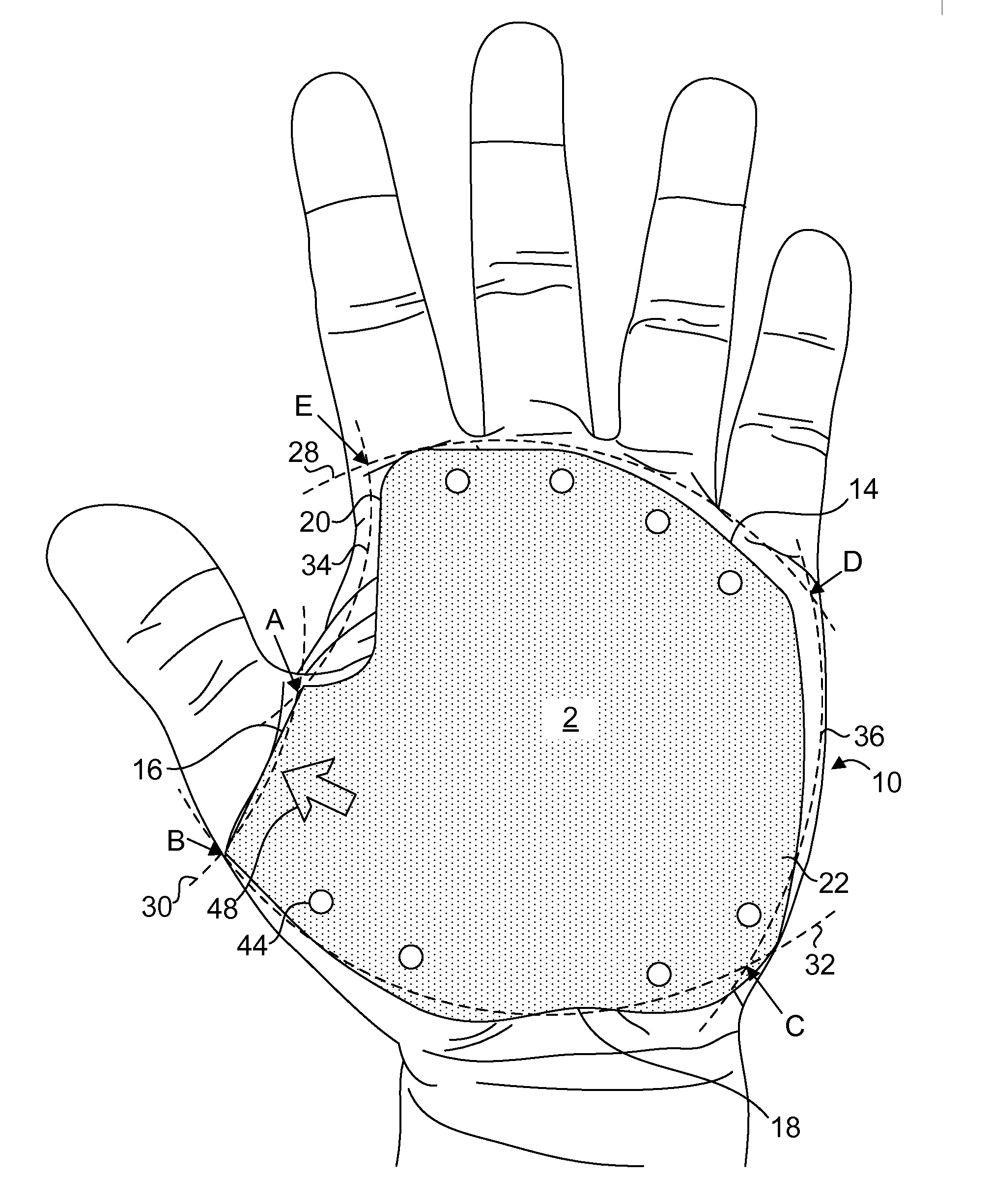
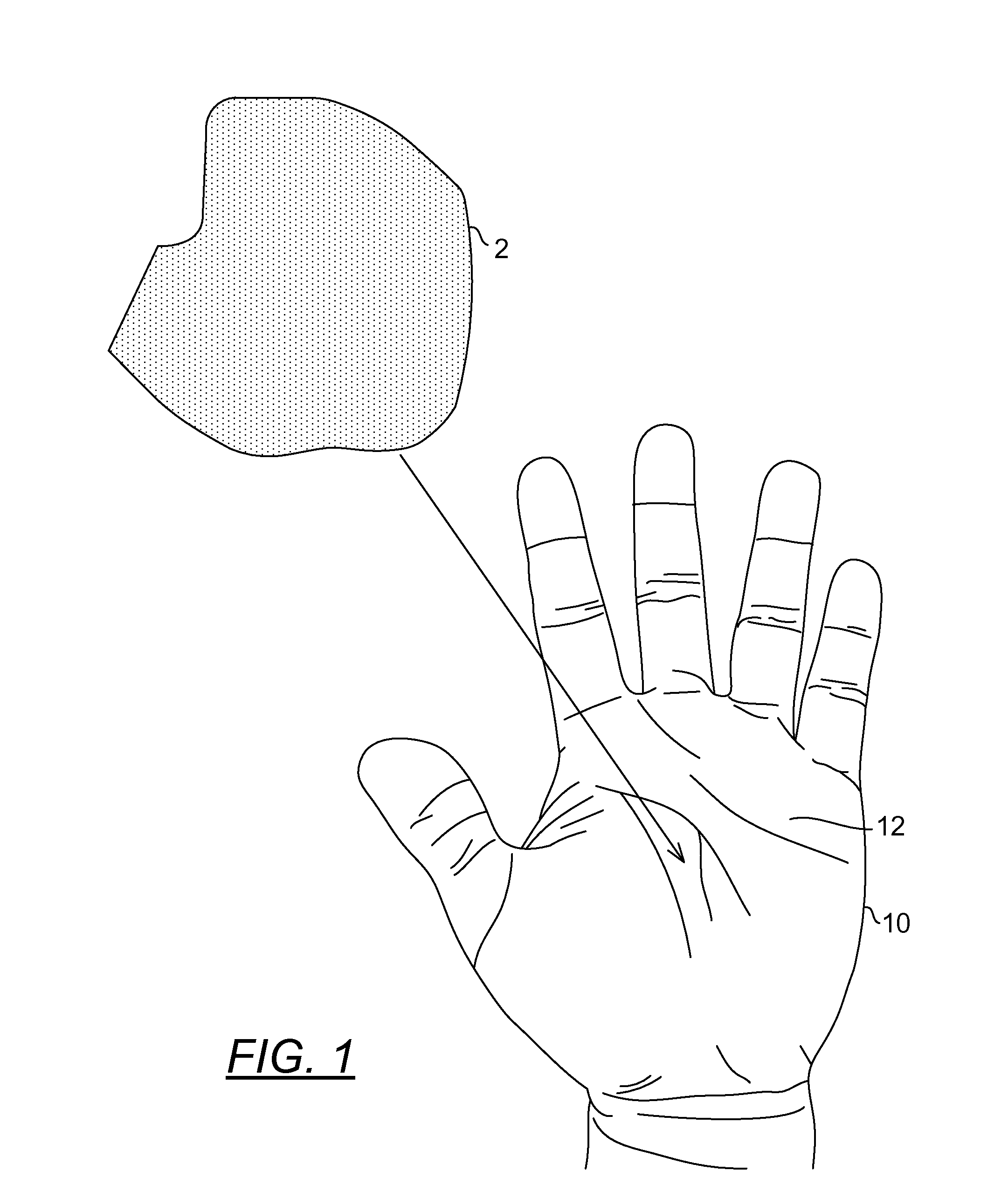
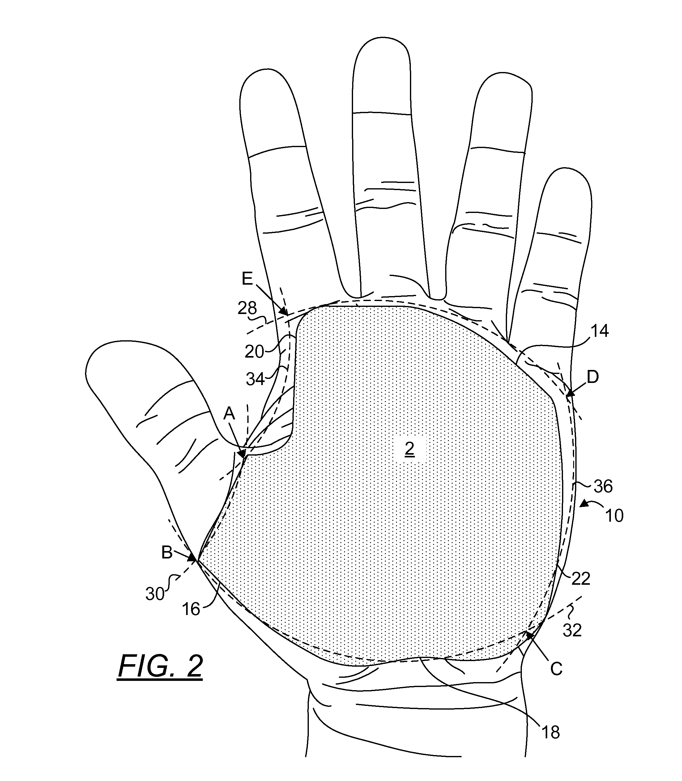
[0055]The term “about” is used herein to mean approximately, roughly, around, or in the region of. When the term “about” is used in conjunction with a numerical range, it modifies that range by extending the boundaries above and below the numerical values set forth. In general, the term “about” is used herein to modify a numerical value above and below the stated value by a variance of 20 percent up or down (higher or lower). FIG. 1 is a top orthogonal view of a present palm glove 2 arranged to be secured to the palm 12 of a left hand 10. FIG. 2 is a top orthogonal view of a present palm glove 2 having been secured to the palm 12 of a left hand 10. A similarly configured glove can be used for a right hand. The glove 2 is configured to cover substantially the entire surface of the palm 12 without affecting the dexterity of the hand 10. The thumb edge 16 of the glove 2 terminates at about the thumb area 30 of the hand 10. The dorsal edge 20 of the glove 2 terminates at about the dorsal area 34 of the hand 10. The finger edge 14 of the glove 2 terminates at about the base of the fingers or finger area 28. The hypothenar edge 22 of the glove 2 terminates at about the hypothenar area 36 of the hand 10. The wrist edge 18 of the glove 2 terminates at about the wrist area 32 of the hand 10. Therefore, the area delineated by the edges 14, 16, 18, 20, 22 is marked by corners A-B-C-D-E as shown in FIG. 2.
[0056]FIG. 3 is a partially transparent view of a gloved hand, depicting the position of a present palm glove 2 relative to a steering wheel 24 of a vehicle grasped using the hand 10. The glove 2 protects the hand by isolating the palm portion of the hand from the wheel and provides enhanced grip of the steering wheel, thereby reducing mistakes due to slippage of the hand from the steering wheel. This is particularly effective for professional or long haul drivers as they must maintain hand contact of the steering wheel for long periods of time. The present glove affords grip and protection without covering the entire or most parts of a hand which can cause user discomfort due to perspiration and moisture and/or heat retention in the cavity of a conventional glove. Another benefit includes the avoidance of bunching as disclosed elsewhere herein. FIG. 4 is a partial sectional view of a gloved palm, depicting creases 40 formed in the palm and a present palm glove conforming to the creases 40. As the glove 2 is attached to the skin 38, the profile of the skin 38 follows that of the glove 2, leaving no gaps for relative movements between the glove 2 and the skin 38. This is unlike conventional gloves where one or more portions of a glove can freely slide on a skin surface, creating bunching and other undesired movements relative to the palm.
[0057]FIG. 5 is a top orthogonal view of a present palm glove. FIG. 6 is a side orthogonal view of a present palm glove, depicting the layers 4, 6, 8 used to form the palm glove 2. In constructing a present glove 2, a substrate layer 4 is chemically, thermally or mechanically bonded to the top surface of a backing layer 6. An attachment layer 8 (with its attachment surface protected using a protective sheet 46 until the glove is ready for use) is bonded to the bottom surface of the backing layer 6, forming a flexible sheet substantially durable to withstand normal uses for such tasks as driving, mowing and other daily chores. Stencils of various suitable palm patterns and sizes are then overlaid atop the substrate layer. Gloves are then cut out of the flexible sheet. As stitching or bonding on the seams is not required for the present gloves, the process for manufacturing them can be fully automated. This is unlike the process for making conventional gloves where manual alignment of various cut pieces must be made in at least one stage of the manufacturing process. The alignment process of making a conventional glove is typically performed by manual labor as it may be technologically or cost prohibitive to automate such a process. While not in use, the glove 2 may be disposed over a protective sheet 46 with the attachment layer 8 coming directly over the protective sheet 46. It is then imperative that the contact surface of the protective sheet 46 be maintained in a clean condition, such that minimal amounts of contaminants such as lint, dust particles, etc. are transferred to the contact surface of the attachment layer 8.
[0058]In one embodiment, the thickness 26 of the present glove 2 is about 1/16 inch. In one embodiment, the substrate layer 4 is a man-made suede available in any colors of consumers' choice. In one embodiment, the substrate layer includes an antimicrobial material.
[0059]In one embodiment, the attachment layer 8 includes a skin-safe medical grade adhesive material. It shall be noted that none of conventional gloves are configured to be attached to a portion of a hand using an adhesive material. Attaching a glove directly human skin presents several challenges. It is important that the adhesive includes a skin compatible composition and not be harsh or aggressive towards the skin or cause skin irritation or inflammation. Also it is preferred if the adhesive is compliant with the skin of the wearer such that maximum skin surface contact between the adhesive and the skin is achieved to securely retain the glove 2 on the palm of a hand. Moreover, it is also desirable to provide an adhesive such that the glove can be readily removed from the wearer, without the wearer experiencing any unacceptable pain level or without causing any tearing of the skin. This is particularly important under circumstances where the device is removed and reapplication of the device once or even a number of times is required for example to allow for better fitment of the glove 2 on the palm of a hand, and to ensure the application of such gloves on sensitive skin, e.g. of an elderly wearer. However, on the other hand the desired level of adhesion, albeit painless should of course also be maintained during such multiple applications of the glove.
[0060]The problem of achieving the desired adhesion level is further exacerbated under wet skin conditions. In some cases, prior to the placement of the device the skin is cleaned and is usually as a result moist. The currently available adhesives, such as those containing hydrocolloid particles, however often do not immediately strongly adhere to the skin and may need to be held in place until sufficient minimum adhesion occurs.
[0061]FIG. 7 is a top orthogonal view of a present palm glove having been secured to the palm of a left hand where cushion patches 42 are disposed on portions of the palm glove 2. FIG. 8 is a side orthogonal view of a present palm glove having been secured to the palm of a left hand where cushion patches 42 are disposed on portions of the palm glove 2. In this embodiment, cushion patches 42 are strategically attached to the substrate layer 4 of the glove 2 to provide comfortable grips to the user. In one embodiment, a cushion patch is constructed from a cotton material and the cushion patch is removably attached to the glove by means of adhesives. In another embodiment, a cushion patch includes gel materials. It shall be noted that the cushion pads 42 are configured sufficiently thin so that the cushion pads do not alter the flexibility of the glove 2 in conforming to the surface curvatures of a palm.
[0062]FIG. 9 is a top orthogonal view of another embodiment of the present palm glove 2 having been secured to the palm of a left hand where through apertures 44 are disposed on portions of the palm glove 2. FIG. 10 is a partial sectional view of a gloved palm, depicting through apertures in every layer of the glove 2 such that portions of the palm to which the glove is attached are exposed. Referring to FIG. 9, a plurality of through apertures 44 are disposed along the finger edge 14 and the wrist edge 18. In other embodiments, through apertures may be disposed anywhere on the glove 2. The diameter of the present through apertures 44 preferably range from 1/16 inch to ¼ inch. In forming the through apertures, a glove is first disposed on a rigid support. A punch of the shape and size of the through apertures is then rapidly lowered onto the glove, pressing the glove against the rigid support and cutting small amounts of material from each layer, i.e., the substrate, backing and adhesive layer, to form a through aperture. In the embodiment shown in FIG. 9, there is further provided an indicium for aiding a user in quickly identifying the correct hand (either left or right) to which a glove is applied. As shown, the indicium is an arrow indicating the direction in which a thumb is disposed upon the glove's attachment to a palm. Alternatively but less desirably, an indicium may simply be a letter “R” or “L” for indicating that a glove is configured for a right or left hand, respectively, as the letters convey their meaning in a less intuitive fashion. An indicium may be formed by a process including but not limited to hot stamping and stitching provided that such process does not significantly alter the stiffness of the flexible sheet.
[0063]The detailed description refers to the accompanying drawings that show, by way of illustration, specific aspects and embodiments in which the present disclosed embodiments may be practiced. These embodiments are described in sufficient detail to enable those skilled in the art to practice aspects of the present invention. Other embodiments may be utilized, and changes may be made without departing from the scope of the disclosed embodiments. The various embodiments can be combined with one or more other embodiments to form new embodiments. The detailed description is, therefore, not to be taken in a limiting sense, and the scope of the present invention is defined only by the appended claims, with the full scope of equivalents to which they may be entitled. It will be appreciated by those of ordinary skill in the art that any arrangement that is calculated to achieve the same purpose may be substituted for the specific embodiments shown. This application is intended to cover any adaptations or variations of embodiments of the present invention. It is to be understood that the above description is intended to be illustrative, and not restrictive, and that the phraseology or terminology employed herein is for the purpose of description and not of limitation. Combinations of the above embodiments and other embodiments will be apparent to those of skill in the art upon studying the above description. The scope of the present disclosed embodiments includes any other applications in which embodiments of the above structures and fabrication methods are used. The scope of the embodiments should be determined with reference to the appended claims, along with the full scope of equivalents to which such claims are entitled.
PUM


Description & Claims & Application Information
We can also present the details of the Description, Claims and Application information to help users get a comprehensive understanding of the technical details of the patent, such as background art, summary of invention, brief description of drawings, description of embodiments, and other original content. On the other hand, users can also determine the specific scope of protection of the technology through the list of claims; as well as understand the changes in the life cycle of the technology with the presentation of the patent timeline. Login to view more.