Electronic cigarette and electronic cigarette device thereof

a technology of electronic cigarettes and electronic cigarettes, which is applied in the direction of tobacco, heating element shapes, electrical appliances, etc., can solve the problems of control switch failure, short circuit, and battery oxidation resistance,

Inactive Publication Date: 2015-06-11
SHENZHEN KIMSEN TECH CO LTD
View PDF6 Cites 105 Cited by
  • Summary
  • Abstract
  • Description
  • Claims
  • Application Information

AI Technical Summary

Benefits of technology

[0004]The objective of the present invention is: to provide an electronic cigarette, which has the function of one-way air path control capable of communicating the air path when inhalation and blocking the air path when blowing.

Problems solved by technology

When users blowing to the electronic cigarette, the aerosol and e-liquid in the atomization device always flow to the battery and the control switch driven by action of airflow, leading to resistance of the battery increasing and electrode oxidation, and then cause short circuit, the control switch failure and so on.

Method used


Image

  • Electronic cigarette and electronic cigarette device thereof
  • Electronic cigarette and electronic cigarette device thereof
  • Electronic cigarette and electronic cigarette device thereof

Examples


first embodiment

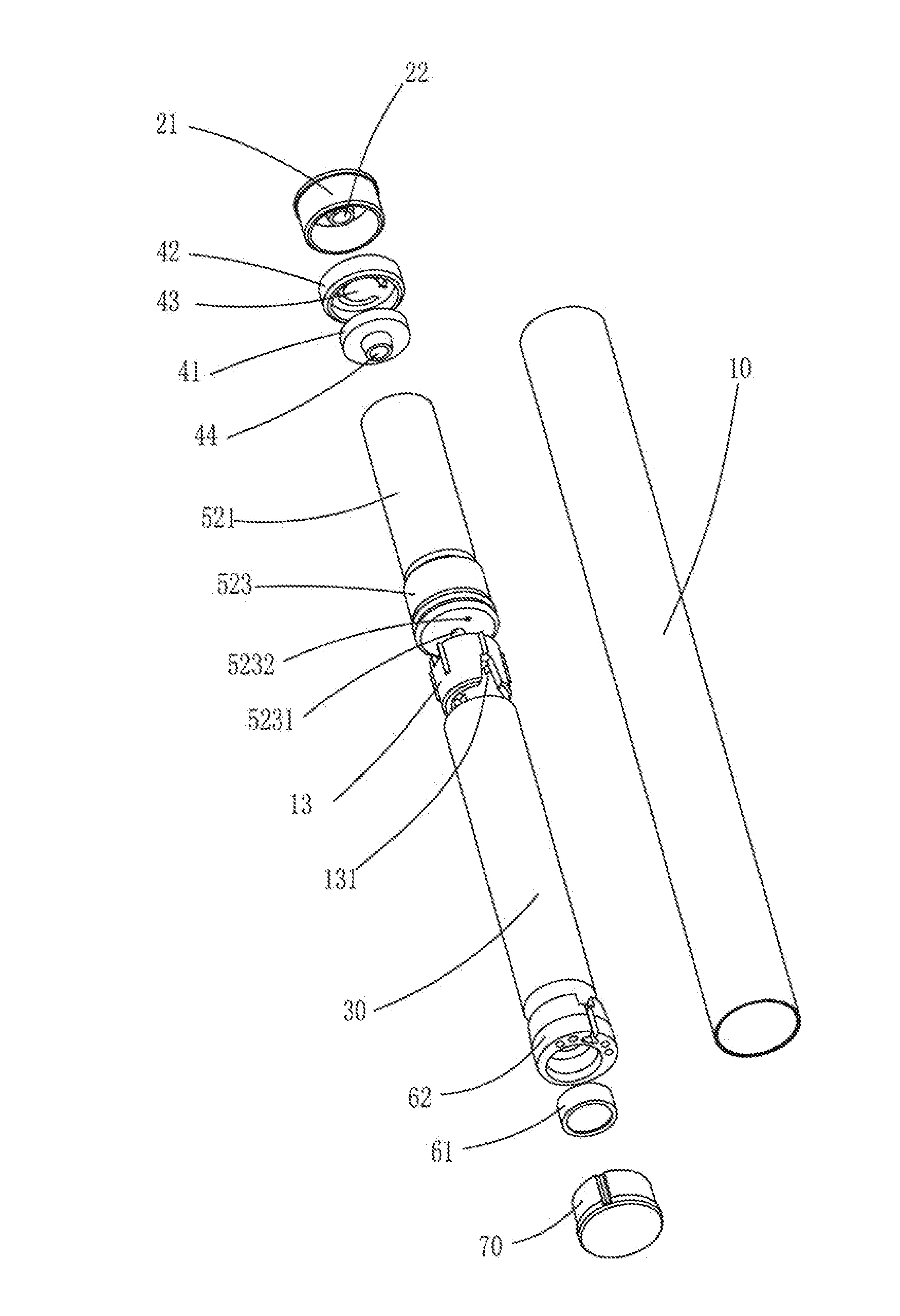
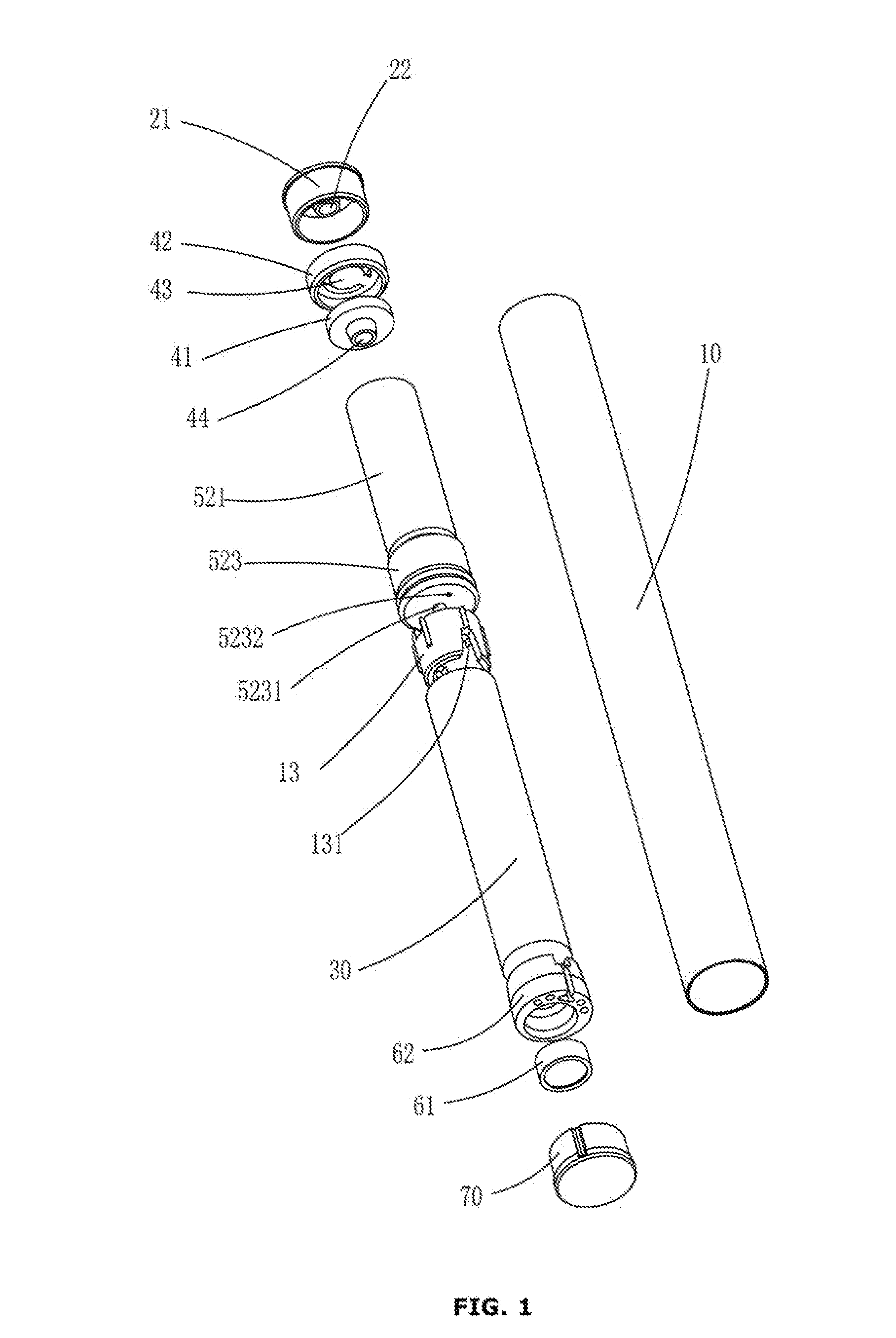
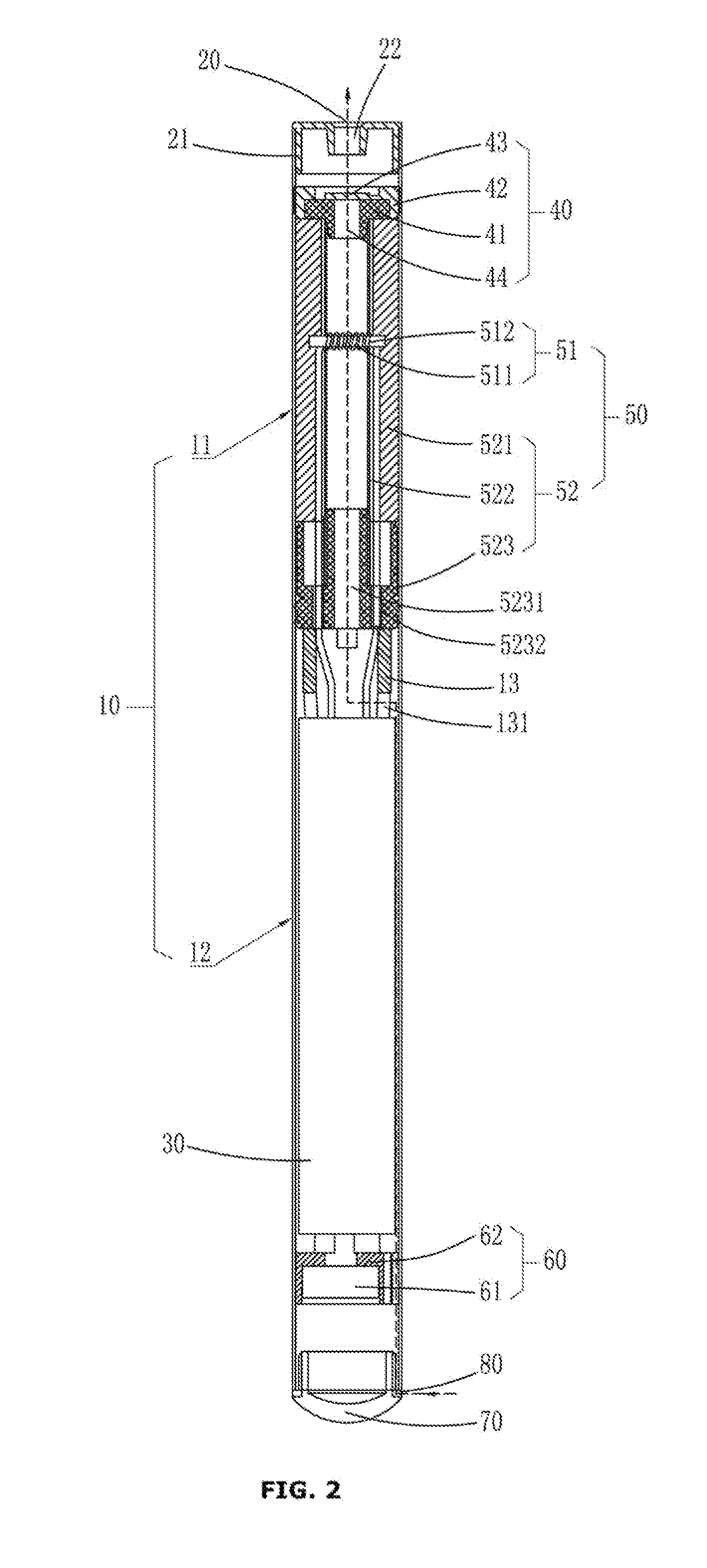
[0043]In a first embodiment as shown in FIG. 6 to FIG. 8, the valve flap 43 is disposed on the valve seat 42, and the gas guide hole 44 is disposed on the valve core 41. Specifically, one side of the valve seat 42 near the valve core 41 disposes a valve core-accommodating groove matching with the outer contour of the valve core 41 to sheath on the valve core 41. The valve core 41 is embedded in the valve core-accommodating groove. The valve flap 43 is attached on the outer surface of the valve core 41 and covers the gas guide hole 44. Referring to FIG. 7 and FIG. 8, the direction of the arrow as shown in the figures is airflow direction. When airflow flows from the valve seat 42 toward the valve core 41, the valve flap 43 is firmly attached on the outside of the port of one end of the gas guide hole 44 under the airflow pressure, then the gas guide hole 44 is closed and the air path is blocked; When airflow flows from the valve core 41 toward the valve seat 42, the valve flap 43 gen...

second embodiment

[0044]In a second embodiment as shown in FIG. 9 to FIG. 11, in the embodiment, the valve flap 43 is disposed on the valve core 41, and the gas guide hole 44 is disposed in the valve seat 42. One side of the valve seat 42 near the valve core 41 disposes a valve core-accommodating groove matching with the outer contour of the valve core 41 to sheath on the valve core 41. The valve core 41 is embedded in the valve core-accommodating groove. The valve flap 43 locates at one side of the valve core 41 near to the valve seat 42 and is attached on the inner surface of the valve core-accommodating groove and completely covers the port of one side of the gas guide hole 44. Referring to FIG. 10 and FIG. 11, the direction of the arrow as shown in the figures is airflow direction. When airflow flows from the valve core 41 toward the valve seat 42, the valve flap 43 is firmly attached on the outside of the port of one end of the gas guide hole 44 under the airflow pressure, then the gas guide hol...


PUM


Abstract

Disclosed are an electronic cigarette and an electronic cigarette device thereof, the electronic cigarette (100) comprising a main rod body (10), one end of the main rod body (10) being provided with a suction nozzle (20) and the other end being internally provided with a battery (30), wherein a one-way valve (40) is further provided in the main rod body (10) between the suction nozzle (20) and the battery (30) for providing a gas passage when inhaling gas and shutting off the gas passage when exhaling gas; the one-way valve (40) comprises a valve seat (42) with two penetrating ends, and a valve core (41) and a valve flap (43) mounted inside the valve seat (42); the valve seat (42) or the valve core (41) is provided with a gas guide hole (44); and the valve flap (43) is affixed to an orifice at one end of the gas guide hole (44) and generates elastic deformation corresponding to the operation of inhaling or exhaling gas so as to control the open or closed state of the gas guide hole. The electronic cigarette (100) has a function of controlling a one-way gas passage, providing the gas passage when inhaling gas and shutting off the gas passage when exhaling gas.

Description

FIELD OF THE INVENTION[0001]The present invention relates to electronic cigarettes and cigarette box, especially an electronic cigarette and electronic cigarette device with a one-way valve mechanism capable of controlling the direction of airflow.BACKGROUND OF THE INVENTION[0002]With further understanding of the harm of smoking by people, quit smoking has become the common goal of most smokers. Then, as a substitute for cigarette, electronic cigarette is gradually welcomed by people.[0003]Current electronic cigarette is usually composed of two parts, including an inhalation rod and a battery rod, wherein the inhalation rod usually disposes a suction nozzle and an atomization device operable to make e-liquid into aerosol. The battery rod usually disposes a battery and a control switch therein. The battery is used to supply power, and the control switch is used to control the overall operation of the electronic cigarette. Air path of current electronic cigarette is completely through...

Claims


Application Information

Patent Timeline
Patent Type & Authority Applications(United States)
IPC IPC(8): A24F47/00A24F15/12H05B1/02A24F15/01A24F40/10A24F40/485
CPCA24F47/008A24F15/12H05B1/0244H05B3/40A24F15/01A24F40/10A24F40/485
Inventor LIU, QIUMING
Owner SHENZHEN KIMSEN TECH CO LTD
Why Eureka
Try Eureka