Electronic Cigarette and Its Sucking Rod

a technology of electronic cigarettes and sucking rods, applied in the field of electronic cigarettes, can solve the problems of inconvenient installation, difficult control of fluid amount, complicated process, etc., and achieve the effects of convenient installation, good drainage and leakproof effect, and simplified fabrication process of electronic cigarettes

Active Publication Date: 2013-12-05
HUIZHOU KIMREE TECH
View PDF6 Cites 217 Cited by
  • Summary
  • Abstract
  • Description
  • Claims
  • Application Information

AI Technical Summary

Benefits of technology

[0004]An object of the present invention is to provide an electronic cigarette sucking rod, it is convenient to be installed, and has good drainage and leakproof effect, and can simplify the fabrication process of t...

Problems solved by technology

Existing electronic cigarettes have the following shortcomings: since the liquid conduit is inserted into the liquid smoke compartment, it is complex and inconvenient to be installed, and easy to lead to leakage, and the fluid amount is also not easy to control.
Secondly, the heating wire is welded or riveted to the conductive wire in advance before it is welded to the copper electrodes of the atomizer, the process is more complicated, and the installation is not easy.
The inhaling passage is disposed at a side of the liquid smoke compartment and...

Method used


Image

  • Electronic Cigarette and Its Sucking Rod
  • Electronic Cigarette and Its Sucking Rod
  • Electronic Cigarette and Its Sucking Rod

Examples


first embodiment

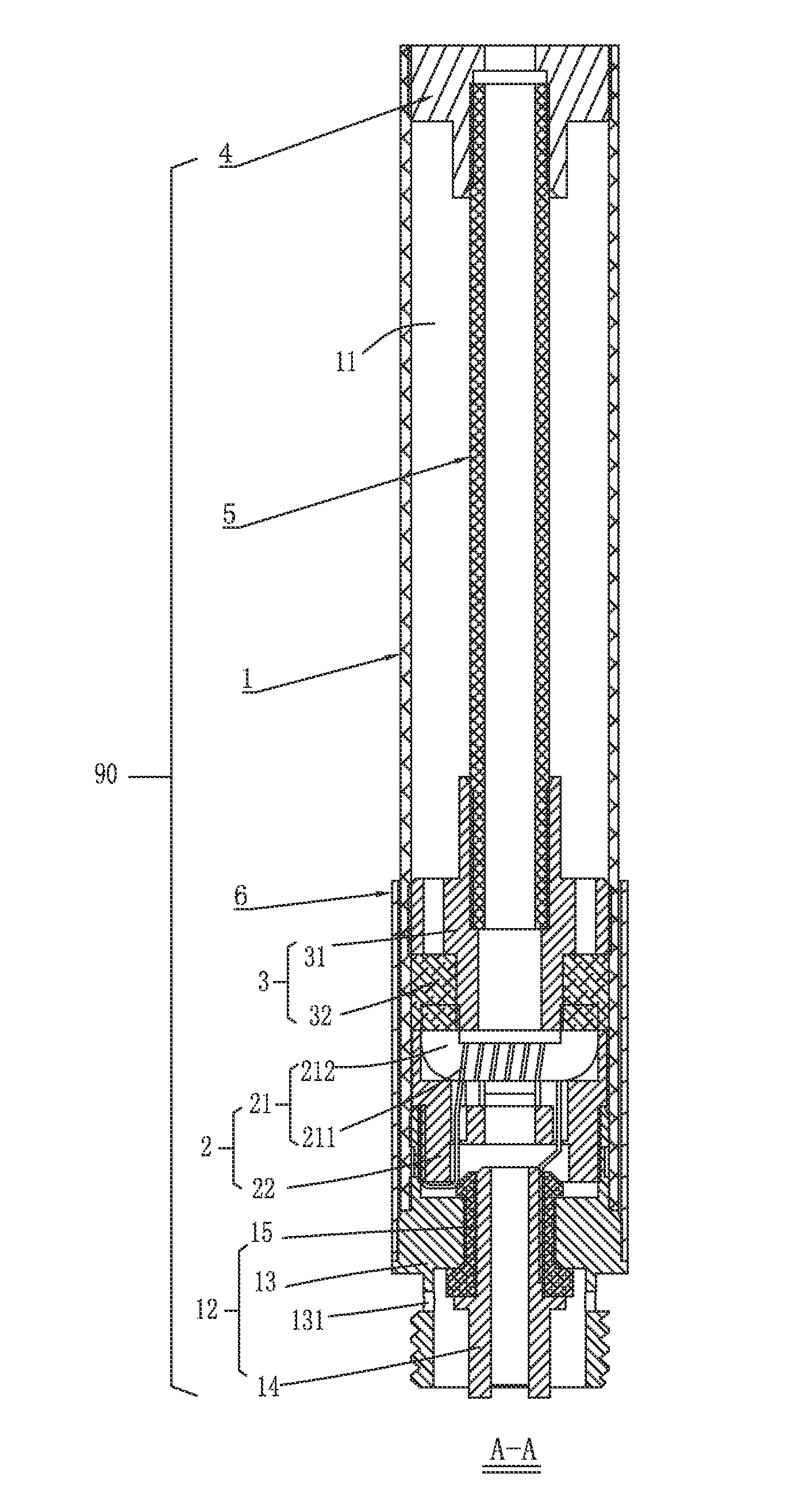
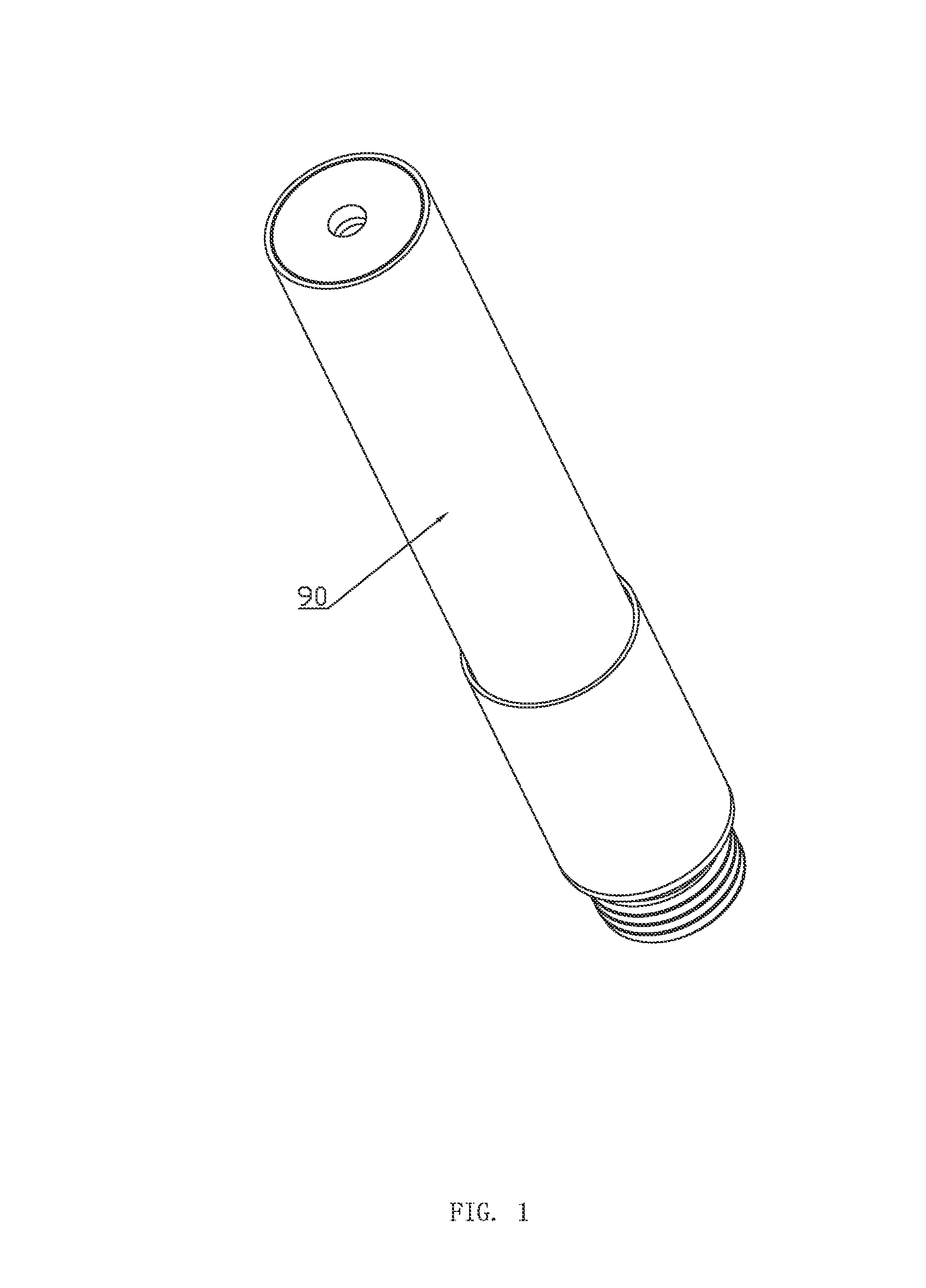
[0043]As shown from FIG. 1 to FIG. 13, an electronic cigarette 100 is provided according to the present invention. The electronic cigarette 100 comprises an electronic cigarette sucking rod 90 and a power rod 91. The electronic cigarette sucking rod 90 and the power rod 91 are connected by fasteners, plugs, screw thread and so on, and in the embodiment by screw thread.

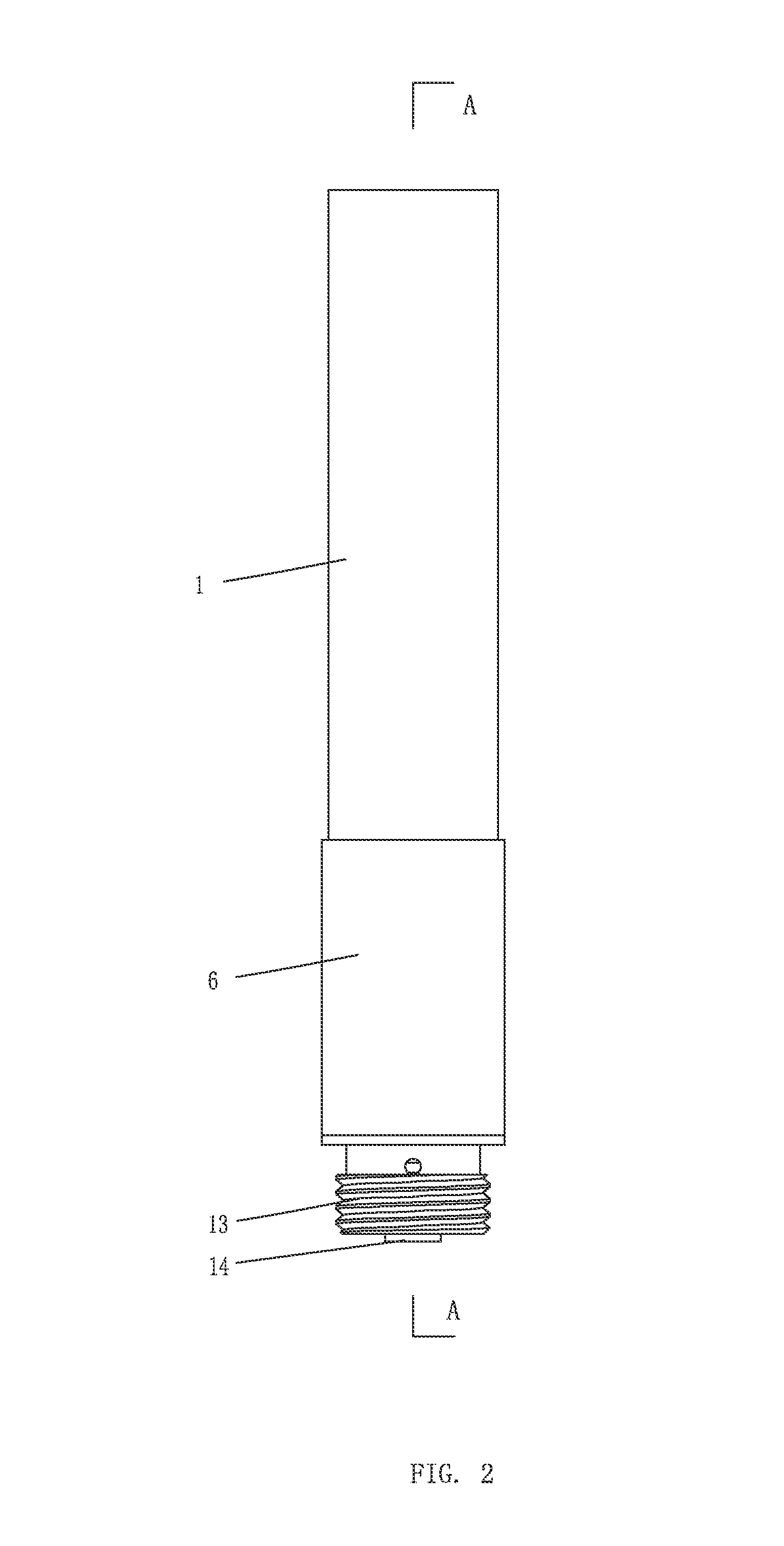
[0044]The electronic cigarette sucking rod 90 comprises a sucking cylinder 1, an atomizing device 2, a liquid guiding component 3 including a liquid separation seat 31 and a liquid reservoir 32, a nozzle cover 4, a conduit 5 and a decorative sleeve 6.

[0045]The sucking cylinder 1 is for installing the atomizing device 2, the liquid guiding component 3, the nozzle cover 4 and the conduit 5. The sucking cylinder 1 has a hollow tubular structure, in the embodiment, it is a cylindrical shell, and is formed by cutting a transparent or translucent elongated tube, and the length of the sucking cylinder 1 can be achieved by cut...

second embodiment

[0059]As shown in FIG. 14, another electronic cigarette sucking rod 90′ is provided according to the present invention, and is similar to the electronic cigarette sucking rod 90 in configuration. The difference between them is that: the nozzle cover 4′ is further provided with a positioning sleeve 7 for positioning the conduit 5, the nozzle cover 4′ and the positioning sleeve 7 both are made of silicone material, and the nozzle cover 4′ has a substantially cylindrical shape, and the nozzle cover 4′ comprises axially extended through hole 41′ and inserting post 42′. The positioning sleeve 7 is substantially cylindrical, and defines a positioning hole 71 axially extended for positioning the conduit 5 and an injecting hole 72 for injecting the liquid smoke into the sucking cylinder 1. The positioning hole 71 is communicated with the through hole 41′, the inserting post 42′ is capable of being inserted into the injecting hole 72. The conduit 5 is inserted into the positioning hole 71 an...


PUM


Abstract

An electronic cigarette sucking rod comprises a nozzle cover and a connecting module respectively inserted into opposite ends of the sucking cylinder, a conduit in the sucking cylinder, a liquid guiding component and an atomizing device between the liquid guiding component and the connecting module; the nozzle cover and the liquid guiding component respectively seal opposite ends of the liquid smoke compartment, opposite ends of the conduit are inserted into the through holes of the nozzle cover and the liquid guiding component, and a smoke passage extends through the liquid guiding component and the conduit. The liquid guiding component comprises a liquid separation seat and a liquid reservoir; the liquid separation seat comprises a seat body and a vent pipe; the vent pipe has its one end engaged with the conduit, and another end sleeved with the liquid reservoir and lead to the atomizing device; the liquid separation seat defines a liquid guiding hole.

Description

TECHNICAL FIELD[0001]This invention relates to a field of electronic cigarettes, and particularly to an electronic cigarette which is ultra-long and transparent.DESCRIPTION OF BACKGROUND[0002]A current electronic cigarette sucking rod comprises: an opaque sucking cylinder, a liquid smoke compartment disposed in the sucking cylinder and integrated with the sucking cylinder, an inhaling passage, an atomizing device disposed in the sucking cylinder and having a heating wire and an atomizing cup, an elongated tubular liquid conduit for guiding the liquid smoke to flow into the atomizing device, a nozzle cover disposed at an end of the sucking cylinder, and an inhaling passage for transmitting the liquid smoke in the atomizing cup to an exterior of the sucking cylinder via the nozzle cover. One end of the liquid conduit is inserted into the liquid smoke compartment, another end of the liquid conduit is inserted into the atomizing device, and the liquid smoke is guided to the atomizing de...

Claims


Application Information

Patent Timeline
IPC IPC(8): A24F47/00A24F40/10A24F40/42A24F40/44A24F40/46A24F40/485
CPCA24F47/008A24F40/46A24F40/10A24F40/44A24F40/42A24F40/485A24B15/167A61M15/06A61M2205/8206A24F47/00
Inventor LIU, QIUMING
Owner HUIZHOU KIMREE TECH
Why Eureka
Try Eureka