Travel support structure

Active Publication Date: 2015-06-11
COOLSIDE LTD
View PDF5 Cites 20 Cited by
  • Summary
  • Abstract
  • Description
  • Claims
  • Application Information

AI Technical Summary

Benefits of technology

[0042]Where the connecting members engage, the connecti

Problems solved by technology

The pillows currently on the market are generally aesthetically unpleasant and have further drawbacks.
For example, the U-shaped pillows generally do not support a user's head at the front below the chin, or at the sides, which causes the chin to fall forward and the neck to lie at an awkward angle, the O-shaped pillows do not cater for a wide enough range of different neck sizes the air filled pillo

Method used


Image

  • Travel support structure
  • Travel support structure
  • Travel support structure

Examples


Example

DETAILED DESCRIPTION OF THE DRAWINGS

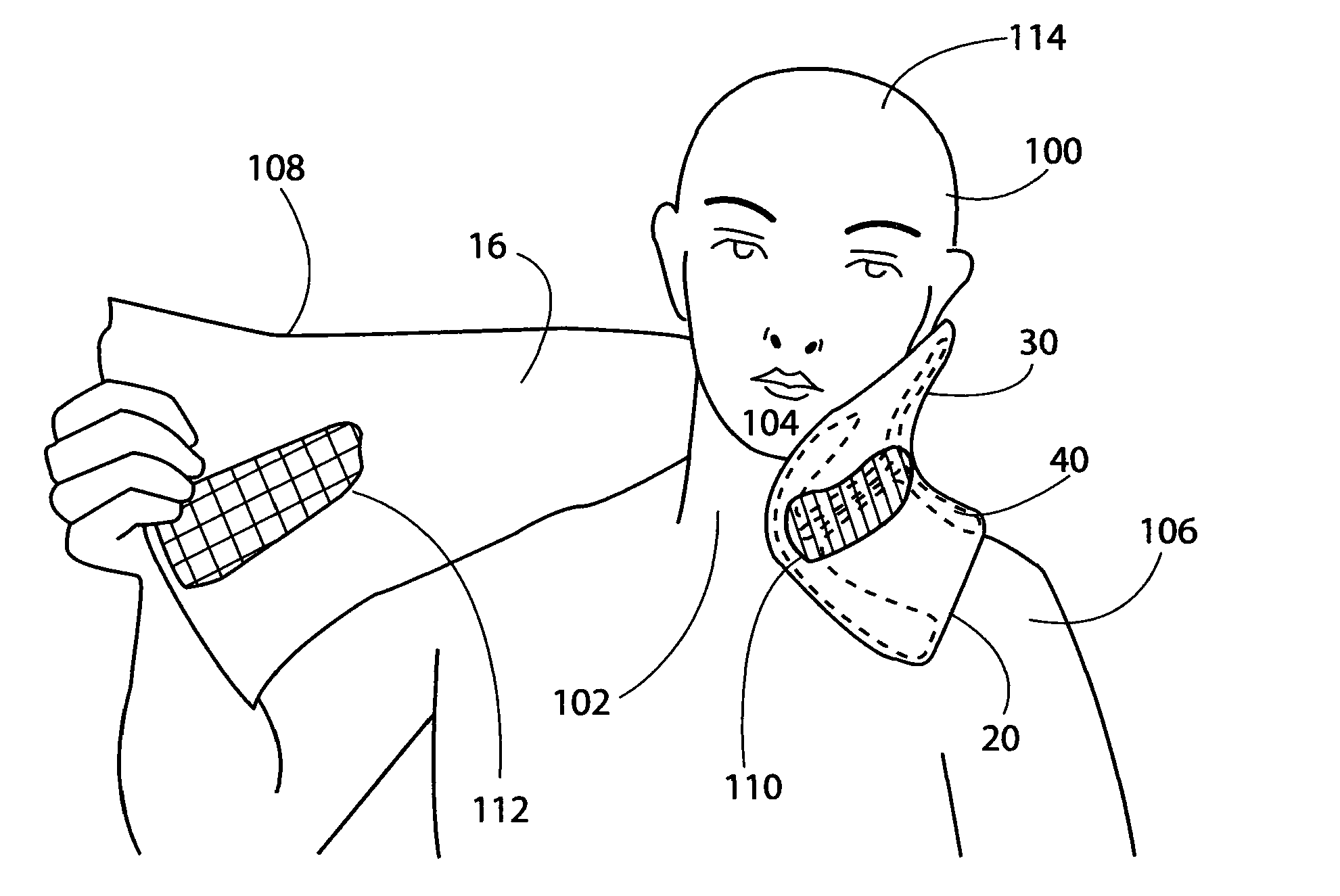
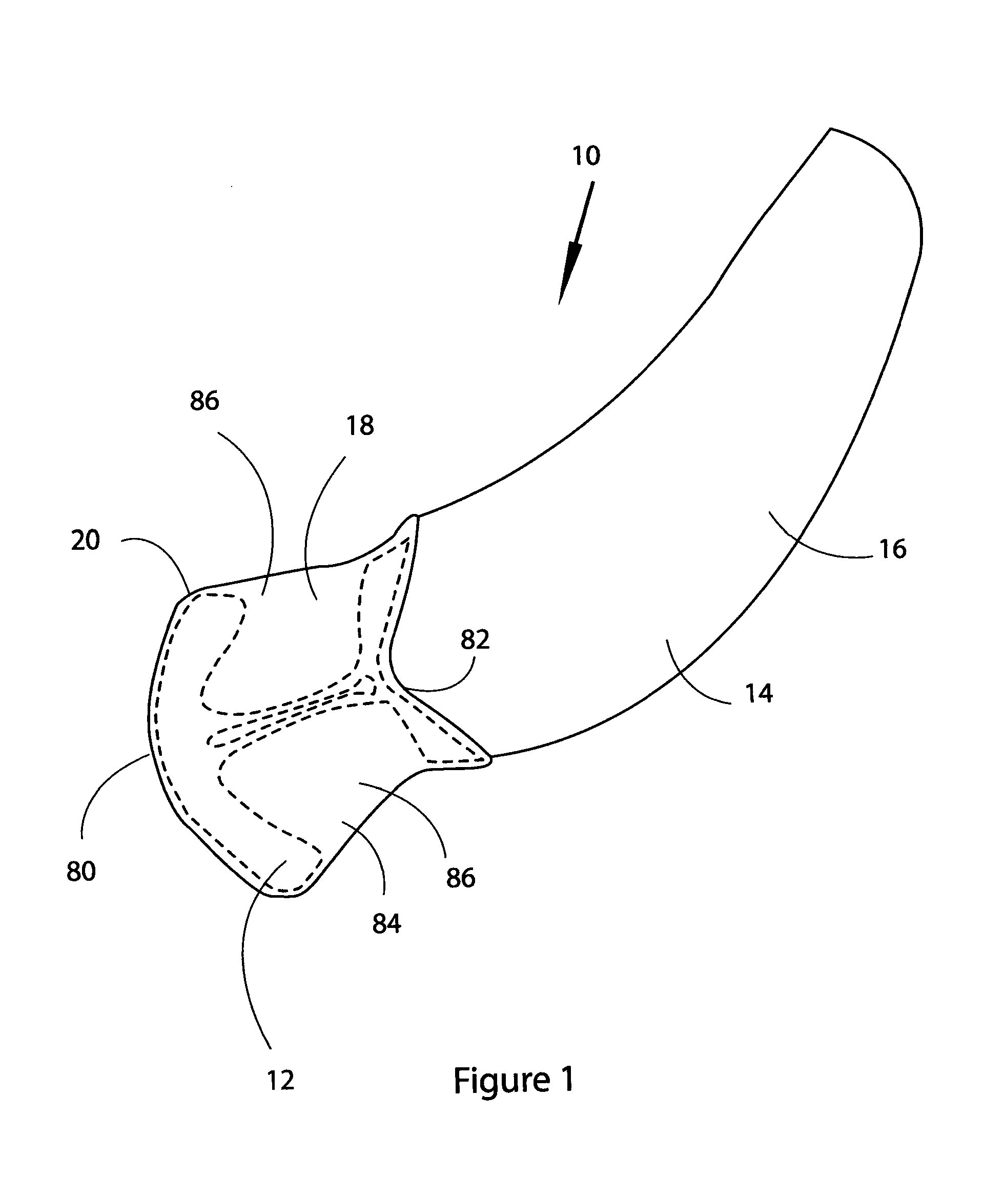
[0053]Referring firstly to FIG. 1, a perspective view of a support structure, generally indicated by reference numeral 10 for at least partially supporting a user's head (not shown) according to a first embodiment of the present invention.

[0054]The support structure 10 comprises a frame 12 and an anchoring means 14 in the form of a scarf 16. The frame 12 is contained within a pocket 18 located at a first end 20 of the scarf 16.

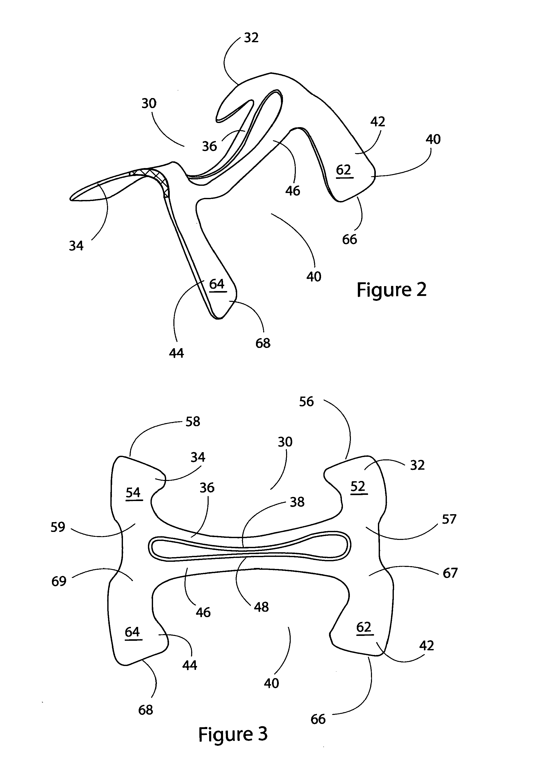
[0055]The frame 12 will now be described in more detail with reference to FIGS. 2, 3, 4 and 5, perspective, top, side and then views of the support structure frame 12 of FIG. 1.

[0056]The frame 12 comprises a single piece of resilient polymeric material and defines a head engaging portion 30 and a shoulder engaging portion 40. As will be shown, the shoulder engaging portion 40 is adapted to spread the load of the user's head over a user's shoulder. The frame 12 is shaped to the contour of the user's body from the head engagin...


PUM


Abstract

A support structure for at least partially supporting a user's head is described. The support structure comprises a frame having a head engaging portion and a shoulder engaging portion, the shoulder engaging portion adapted to spread the load of the user's head over a user's shoulder, the frame being shaped to the contour of the user's body from the head engaging portion to the shoulder engaging portion.

Description

FIELD OF THE INVENTION[0001]The present invention relates to a support structure for at least partially supporting a user's head when travelling. Particularly, the support structure is to at least partially support a user's head when sleeping whilst sitting in a relatively upright position.BACKGROUND TO THE INVENTION[0002]The use of travel pillows is common practice for passengers in cars, planes, buses and trains. There are four main types of travel pillow, currently on the market: memory foam pillows, polystyrene bead filled pillows, air filled pillows and feather or stuffing filled pillows.[0003]These pillows come in various forms, but generally fall into one of three categories: C-shaped, O-shaped, or L shaped.[0004]The pillows currently on the market are generally aesthetically unpleasant and have further drawbacks. For example, the U-shaped pillows generally do not support a user's head at the front below the chin, or at the sides, which causes the chin to fall forward and the...

Claims


Application Information

Patent Timeline
IPC IPC(8): A47C7/38B60N2/48
CPCB60N2/48A47C7/38A47C7/383A47G9/10B60N2/80A47C16/00
Inventor KELLOCK, DAVIDCORRIGAN, MICHAEL
Owner COOLSIDE LTD
Why Eureka
Try Eureka