Post-implant expandable surgical heart valve configurations

Active Publication Date: 2014-07-03
EDWARDS LIFESCIENCES CORP
View PDF1 Cites 22 Cited by
  • Summary
  • Abstract
  • Description
  • Claims
  • Application Information

AI Technical Summary

Benefits of technology

This patent describes a prosthetic heart valve that can be expanded from a small, unexpanded configuration to a larger, expanded configuration. The prosthetic heart valve has a support structure that resists inward compression when in the unexpanded configuration, but can expand when subjected to a dilation force. The support structure is made up of a first inner band and a second outer band that pass around the support structure. The prosthetic heart valve can be securely positioned within a patient's heart using a percutaneous delivery system. The prosthetic heart valve can be made of a flexible material that allows for elastic expansion and contraction. This allows for the prosthetic heart valve to adapt to the patient's individual needs and remain secure in the heart.

Problems solved by technology

Diseased heart valves may be categorized as either stenotic, wherein the valve does not open sufficiently to allow adequate forward flow of blood through the valve, and / or incompetent, wherein the valve does not close completely, causing excessive backward flow of blood through the valve when the valve is closed.
Valve disease can be severely debilitating and even fatal if left untreated.
For example, a prosthetic heart that was successfully implanted to replace a native valve may itself suffer damage and / or wear and tear many years after initially being implanted.
Implanting the prosthetic heart valve directly within a previously-implanted prosthetic heart valve may be impractical, in part because the new prosthetic heart valve (including the support structure and valve assembly) will have to reside within the annulus of the previously-implanted heart valve, and traditional prosthetic heart valves may not be configured to easily receive such a valve-within-a-valve implantation in a manner which provides secure seating for the new valve while also having a large enough annulus within the new valve to support proper blood flow therethrough.

Method used


Image

  • Post-implant expandable surgical heart valve configurations
  • Post-implant expandable surgical heart valve configurations
  • Post-implant expandable surgical heart valve configurations

Examples


Embodiment Construction

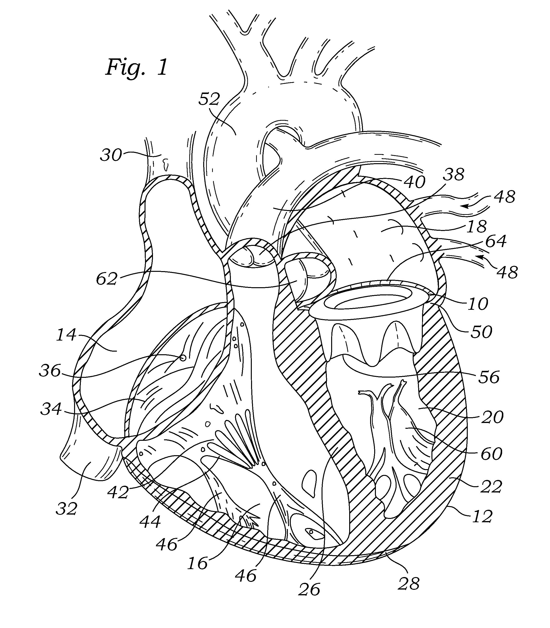
[0064]With reference to FIG. 1, a prosthetic heart valve 10 according to the invention is depicted in a heart 12. The heart 12 has four chambers, known as the right atrium 14, right ventricle 16, left atrium 18, and left ventricle 20. The general anatomy of the heart 12, which is depicted as viewed from the front of a patient, will be described for background purposes. The heart 12 has a muscular outer wall 22, with an interatrial septum 24 dividing the right atrium 14 and left atrium 18, and a muscular interventricular septum 26 dividing the right ventricle 16 and left ventricle 20. At the bottom end of the heart 12 is the apex 28.

[0065]Blood flows through the superior vena cava 30 and the inferior vena cava 32 into the right atrium 14 of the heart 12. The tricuspid valve 34, which has three leaflets 36, controls blood flow between the right atrium 14 and the right ventricle 16. The tricuspid valve 34 is closed when blood is pumped out from the right ventricle 16 through the pulmon...


PUM

PropertyMeasurementUnit
Forceaaaaaaaaaa
Diameteraaaaaaaaaa
Structureaaaaaaaaaa

Abstract

Disclosed herein is a prosthetic heart valve, and associated methods therefore, configured to replace a native heart valve, and having a support frame configured to be reshaped into an expanded form in order to receive and / or support an expandable prosthetic heart valve therein. The prosthetic heart valve is configured to have an expansion-resistant configuration when initially implanted to replace a native valve (or other prosthetic heart valve), but to assume a generally expanded form when subjected to an outward force such as that provided by a dilation balloon or other mechanical expander.

Description

RELATED APPLICATIONS[0001]The present application claims priority under 35 U.S.C. §119 to U.S. Provisional Application Ser. No. 61 / 748,022, filed Dec. 31, 2012. The present application is also related to U.S. patent application Ser. No. 12 / 234,559, filed Sep. 19, 2008, entitled “Prosthetic Heart Valve Configured to Receive a Percutaneous Prosthetic Heart Valve Implantation,” and related to U.S. patent application Ser. No. 12 / 234,580, filed Sep. 19, 2008, entitled “Annuloplasty Ring Configured to Receive a Percutaneous Prosthetic Heart Valve Implantation,” the entire disclosures of which are expressly incorporated herein by reference.FIELD OF THE INVENTION[0002]The present invention relates to a surgical heart valve for heart valve replacement, and more particularly to a surgical heart valve configured to receive an expandable prosthetic heart valve therein.BACKGROUND OF THE INVENTION[0003]The heart is a hollow muscular organ having four pumping chambers separated by four heart valve...

Claims


Application Information

Patent Timeline
IPC IPC(8): A61F2/24
CPCA61F2/2418A61F2/2445A61F2220/0033A61F2220/0075A61F2250/0063A61F2250/0071A61F2250/0004A61F2210/0004A61F2310/00011A61F2250/001A61F2250/006A61F2210/0014A61F2/2409A61F2/2433
Inventor CONKLIN, BRIAN S.CAMPBELL, LOUIS A.BOBO, JR., DONALD E.FORD, STEVEN M.JOHNSON, DERRICK
Owner EDWARDS LIFESCIENCES CORP
Why Eureka
Try Eureka