Packaging equipment

A technology of packaging equipment and charging box, which is applied in the directions of packaging, transportation packaging, and food packaging, can solve the problems of manual packaging, such as labor-intensive, unprotected hygiene, and hidden hygiene problems, and achieve smooth transportation and good hygiene conditions. Guaranteed, low noise effect

Inactive Publication Date: 2021-06-25
李萍
View PDF0 Cites 0 Cited by
  • Summary
  • Abstract
  • Description
  • Claims
  • Application Information

AI Technical Summary

Problems solved by technology

[0004] Manual packaging has disadvantages such as high labor intensity, low efficiency, and lack of hygiene protection. There are also very few large-scale enterprises that have introduced automatic packaging machines. An automatic packaging machine that realizes roll-type packaging currently exists on the market is a simulated cigarette machine. Its structure and principle are large and costly, so it is not suitable for promotion in small and medium-sized enterprises; some automatic packaging machines still use manual feeding, and the packaging speed is slow, which does not fundamentally solve the problems of manual packaging.
[0005] In addition, the current automatic packaging machines still have a common deficiency: they need to be lubricated with grease during the working process. Although food packaging machinery generally uses edible oil for lubrication, the grease attached to the mechanical parts is easy to breed bacteria, Accumulation of dust, there is a health hazard

Method used


Image

  • Packaging equipment
  • Packaging equipment
  • Packaging equipment

Examples


Embodiment 1

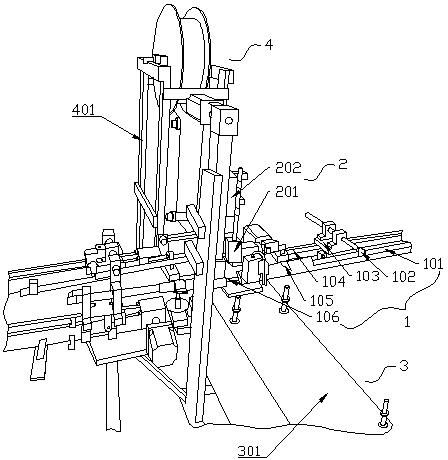
[0062] Such as figure 1 As shown, the present embodiment provides a packaging device, including a feeding part 1, a feeding part 2 and a packaging part 3, and the feeding part 2 is located between the feeding part 1 and the packaging part 3 and accepts the feeding part 1 and the packaging part 3. The packing part 3 and one side of the unloading part 2 are provided with a paper feeding mechanism 4 .

[0063] Specifically, the feeding part 1 includes a feeding trough 101 for carrying materials, and one side of the feeding trough 101 is provided with a pushing plate 102 for pushing the materials forward.

[0064] Such as figure 2 As shown, the feed trough 101 is in the shape of a strip, the end of the feed trough 101 close to the briquetting block 201 is a tubular structure, and the rest of the feed trough 101 is a groove structure with an open top; the feed trough 101 tubular structure is close to The end surface of the pressing block 201 is a forward inclined surface, and on...

Embodiment 2

[0095] The features of this embodiment that are the same as those of Embodiment 1 will not be described in detail. The features of this embodiment that are different from Embodiment 1 are: Image 6 , Figure 7 As shown, in this embodiment, one side of the second roller 304 is provided with a third roller 307, and the third roller 307 is located on the side of the second roller 304 away from the first roller 303, and the first roller Outer edges of the shaft 303 , the second roller shaft 304 and the third roller shaft 307 protrude above the charging box 302 . The third roller 307 can share the pressure and friction force applied to the second roller 304 by the top surface of the packaging channel 301 , so as to slow down the wear of the second roller 304 and prolong the service life of the charging box 302 .

Embodiment 3

[0097] The features of this embodiment that are the same as those of the preceding embodiments will not be described in detail. The features of this embodiment that are different from those of the preceding embodiments are as follows: Figure 9 As shown, in this embodiment, the side wall of the charging box 302 and the bottom surface 311 form a flexible connection so that the side wall has a degree of freedom of movement in the axial direction of the first roller shaft 303, and the two sides of the charging box 302 One or more springs 312 are connected between the two side walls.

[0098] Specifically, the mounting hole connecting the bottom surface 319 of the charging box 302 with the side wall in this embodiment is an oblong hole 320, the first roller 303, the second roller 304, the third roller 307, the first roller 305 and the second roller The two ends of the two rollers 306 leave a movable space for the side walls of the charging box 302 to realize the change of the dist...


PUM


Abstract

The invention discloses packaging equipment, and belongs to the technical field of goods packaging. The packaging equipment structurally comprises a feeding part, a discharging part and a packaging part, wherein the discharging part is located between the feeding part and the packaging part and is used for bearing the feeding part and the packaging part, and a paper feeding mechanism is arranged at one side of the discharging part; the feeding part comprises a feeding groove for bearing materials, and a material pushing plate for pushing the materials to advance is arranged at one side of the feeding groove; and the discharging part comprises a pressing block for pressing the materials into a charging box, the packaging part comprises a packaging channel, the packaging channel is located on the moving track of the charging box, and the inner surface of a top plate of the packaging channel is a rough surface in order to rub the packaged materials in the charging box to rotate. According to the technical scheme, the packaging equipment is simple in structure, small in size, low in noise and low in cost, can better replace manual work to conduct winding drum type packaging on goods, conforms to the technical development trend of automation and digitization, and is supported by the country.

Description

technical field [0001] The invention relates to the technical field of article packaging, in particular to a packaging device, especially suitable for packaging of sliced ​​food or small piece of food. Background technique [0002] "Packaging" is not unfamiliar to people. Various items with packaging can be seen everywhere in life. Roll packaging is a relatively common packaging method. Generally, aluminum foil paper is tightly wound on the packaged It is often found on the surface of food, such as hawthorn slices, etc., which are packaged in small portions. [0003] As a food suitable for all ages, hawthorn slices have a long history in our country and are loved by many people until now. At present, most of the enterprises engaged in the production of hawthorn slices are small and medium-sized enterprises. But still mostly rely on manual packaging. [0004] Manual packaging has disadvantages such as high labor intensity, low efficiency, and lack of hygiene protection. Th...

Claims


Application Information

Patent Timeline
Patent Type & Authority Applications(China)
IPC IPC(8): B65B11/04B65B41/16B65B61/06B65B57/08B65B25/00
CPCB65B11/04B65B25/001B65B41/16B65B57/08B65B61/06
Inventor 李萍李怀国陆平
Owner 李萍
Why Eureka
Try Eureka