
Rotor of an Electric Generator for Generating Electricity in Power Plants

Inactive Publication Date: 2015-06-11
SENSOPLAN
View PDF10 Cites 1 Cited by
  • Summary
  • Abstract
  • Description
  • Claims
  • Application Information

AI Technical Summary

Benefits of technology

The patent describes how to improve the cooling of generator rotors with indirectly cooled rotor winding. The cooling channels in the support elements are designed to avoid dead water spaces and improve heat dissipation. A uniform spacing of the spacers ensures an interruption-free and complete flow through the cooling channels. The support elements are stiff and almost isotropic because the spacings between the spacers are smaller than prior to this and all elements are oriented in axial direction. Another embodiment proposes that for a new winding with new conductors also the coil spacings can be varied additionally to reinforce the cooling performance.

Problems solved by technology

This reduces the service life as well as the operational performance.
The disadvantageous undulated guiding action for the cooling air about the triangular spacers between the coils in axial as well as tangential direction causes large dead spaces and thus large surface areas that are not flowed across by the cooling medium.
This causes an increased temperature within the conductors.
Moreover, these undulated cooling air channels cause strong gradients in the speed profile.
Areas are produced with excellent and with bad heat dissipation and thus non-uniform temperature.
Temperature gradients cause thermal stress in the conductors and thus cause rough running of the rotor.
Moreover, an unfavorable sizing of the thickness of the support elements impairs a sufficient supply with cooling air.
This is so because greater bracket lengths in tangential direction and in axial direction entail longer conductors and thus higher losses because the resistance increases proportional to the length.
This is disadvantageous for larger coils.
With regard to mechanical aspects, the known support elements also have weaknesses.
In this way, an anisotropic stiffness of the winding overhang support results.
This disadvantageous support of the coils causes movements in the winding overhang in operation and thus causes rough running of the rotor.

Method used


Image

  • Rotor of an Electric Generator for Generating Electricity in Power Plants
  • Rotor of an Electric Generator for Generating Electricity in Power Plants
  • Rotor of an Electric Generator for Generating Electricity in Power Plants

Examples


Embodiment Construction

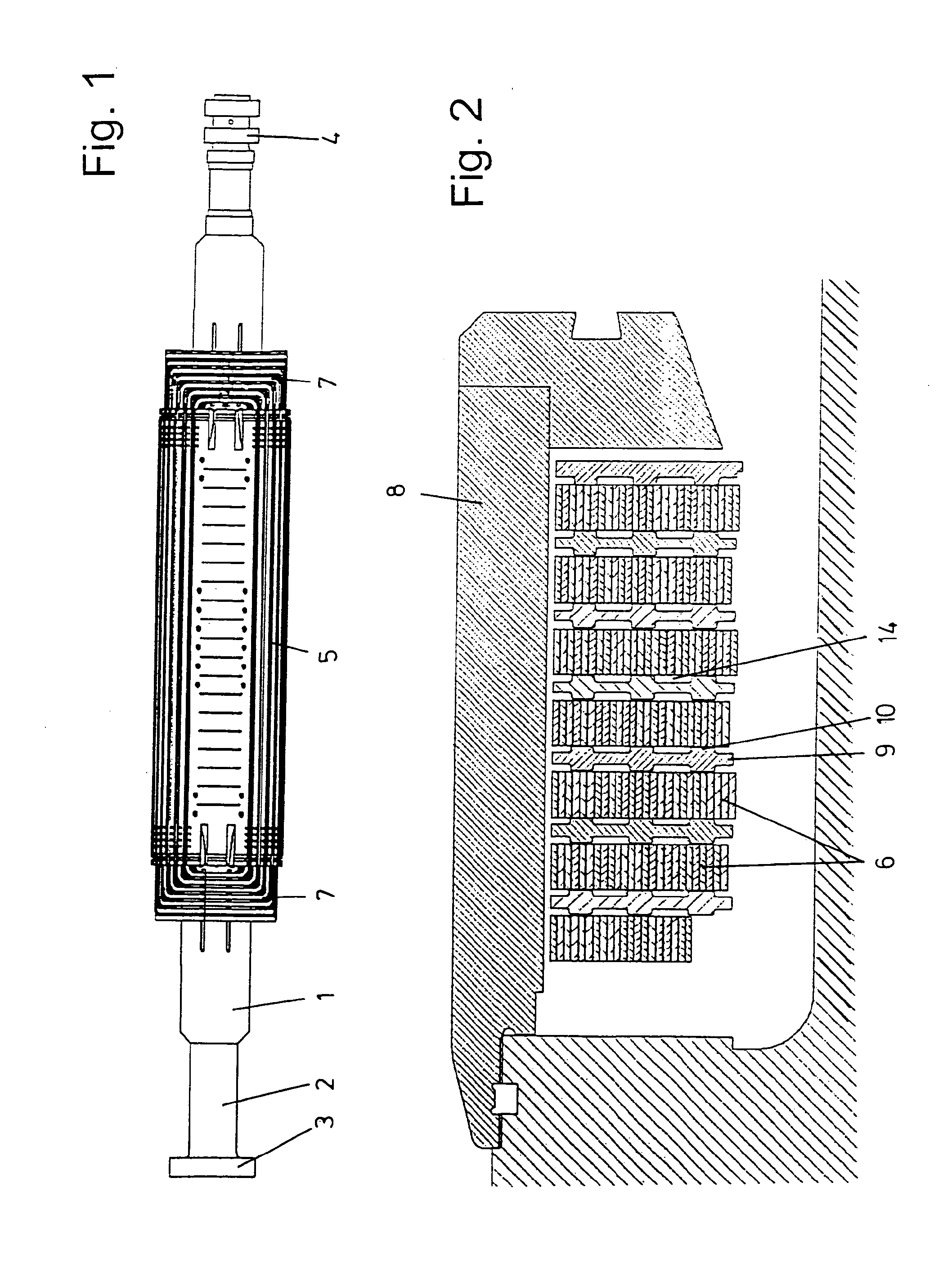
[0039]FIG. 1 shows the rotor of a 2-pole generator as a whole. In this context, the rotor has a shaft 1. The latter has at one end a bearing 2 as well as a coupling 3 for the turbine and at the other end slide rings 4. In the central area there is the rotor body with the rotor winding 5 comprised of individual conductors 6. The two ends of the rotor winding 5 form the winding overhangs 7. It can be seen additionally in FIG. 2 that the winding overhangs 7 are covered by a rotor cover 8.

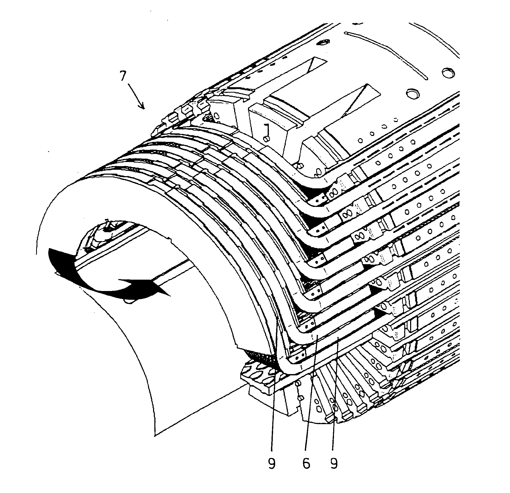
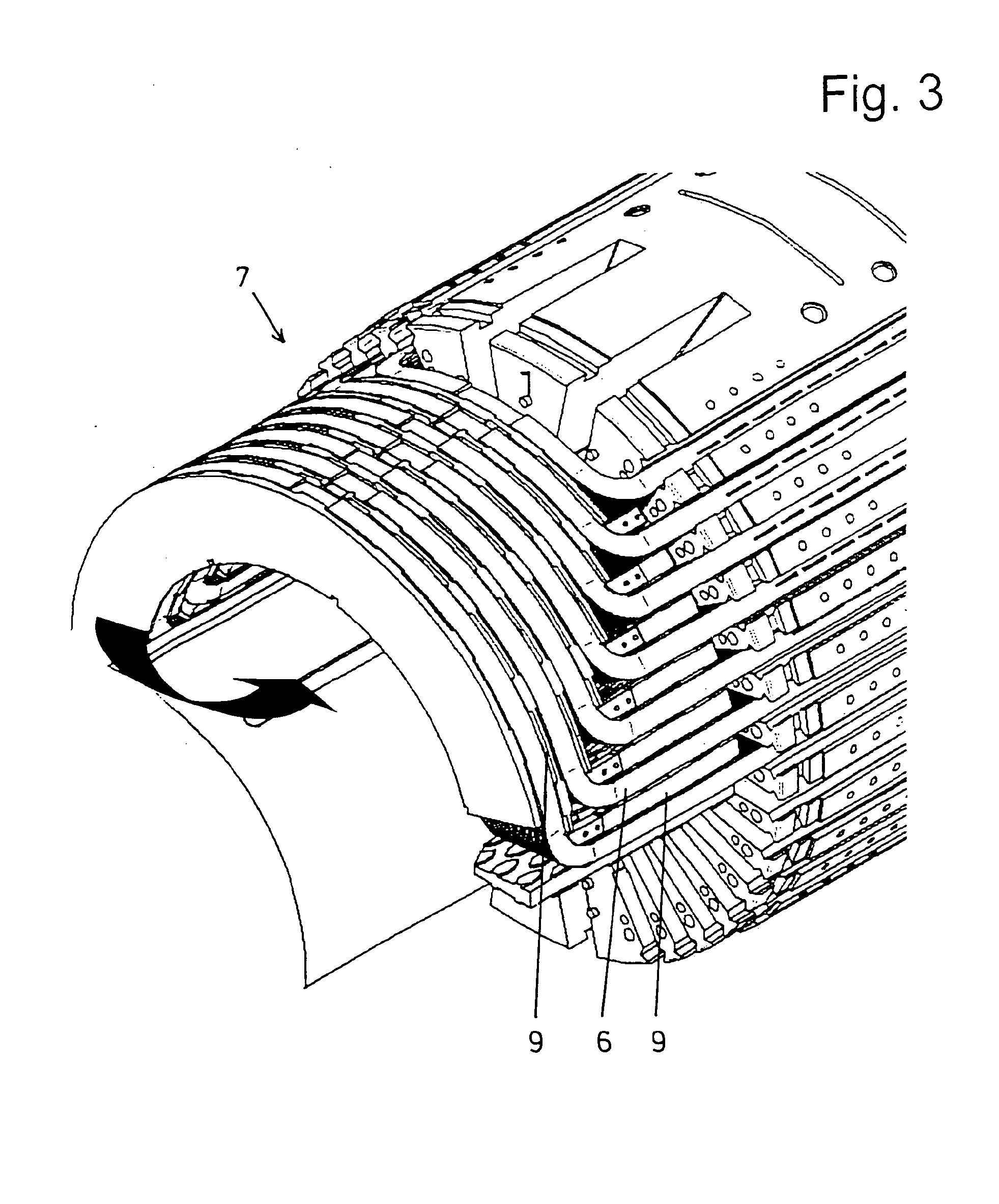
[0040]As can be seen in detail in FIGS. 3 to 5, the conductors 6 are arranged in the area of the winding overhang 7 initially straight and coaxial to the axis of the shaft 1, subsequently circular arc-shaped and concentric, and finally straight and coaxial again. In the straight area as well as in the circular arc-shaped area of the conductors 6 there are between them—in the most general sense—plate-shaped flat support elements 9 of fiberglass-reinforced plastic material or another insulating material....


PUM


Abstract

The invention relates to a rotor of an electric generator for generating electricity in power plants, with support elements (9) having spacers (10) between the conductors (6) in the area of the winding overhang (7). The spacers (10) are distributed over the surface of the support elements (9) as island-shaped structures so that the conductors can be cooled uniformly.

Description

CROSS-REFERENCE TO RELATED APPLICATIONS[0001]This application is a divisional application of U.S. application Ser. No. 13 / 497,411 having a filing dated of 21 Mar. 2012, which is a national stage filing of international application No. PCT / DE2010 / 001309 having an international filing date of 10 Nov. 2010 designating the United States, the international application claiming a priority date of 18 Dec. 2009, based on prior filed German patent application No. 10 2009 058 830.2, the entire contents of the aforesaid United Sates patent application, the aforesaid international application, and the aforesaid German patent application being incorporated herein by reference.BACKGROUND OF THE INVENTION[0002]The invention concerns a rotor of an electric generator for generating electricity in power plants with a shaft, with conductors arranged on the shaft and defining a winding of coils, with plate-shaped support elements of an electrically insulating material arranged in the area of the windin...

Claims


Application Information

Patent Timeline
IPC IPC(8): H02K3/38H02K3/24
CPCH02K3/24H02K3/38H02K3/12H02K3/505H02K9/00
Inventor SCHUBERT, JOHANN
Owner SENSOPLAN
Learn More