Induced draft fan and gas furnace comprising the same
- Summary
- Abstract
- Description
- Claims
- Application Information
AI Technical Summary
Benefits of technology
Problems solved by technology
Method used
Image
Examples
example 1
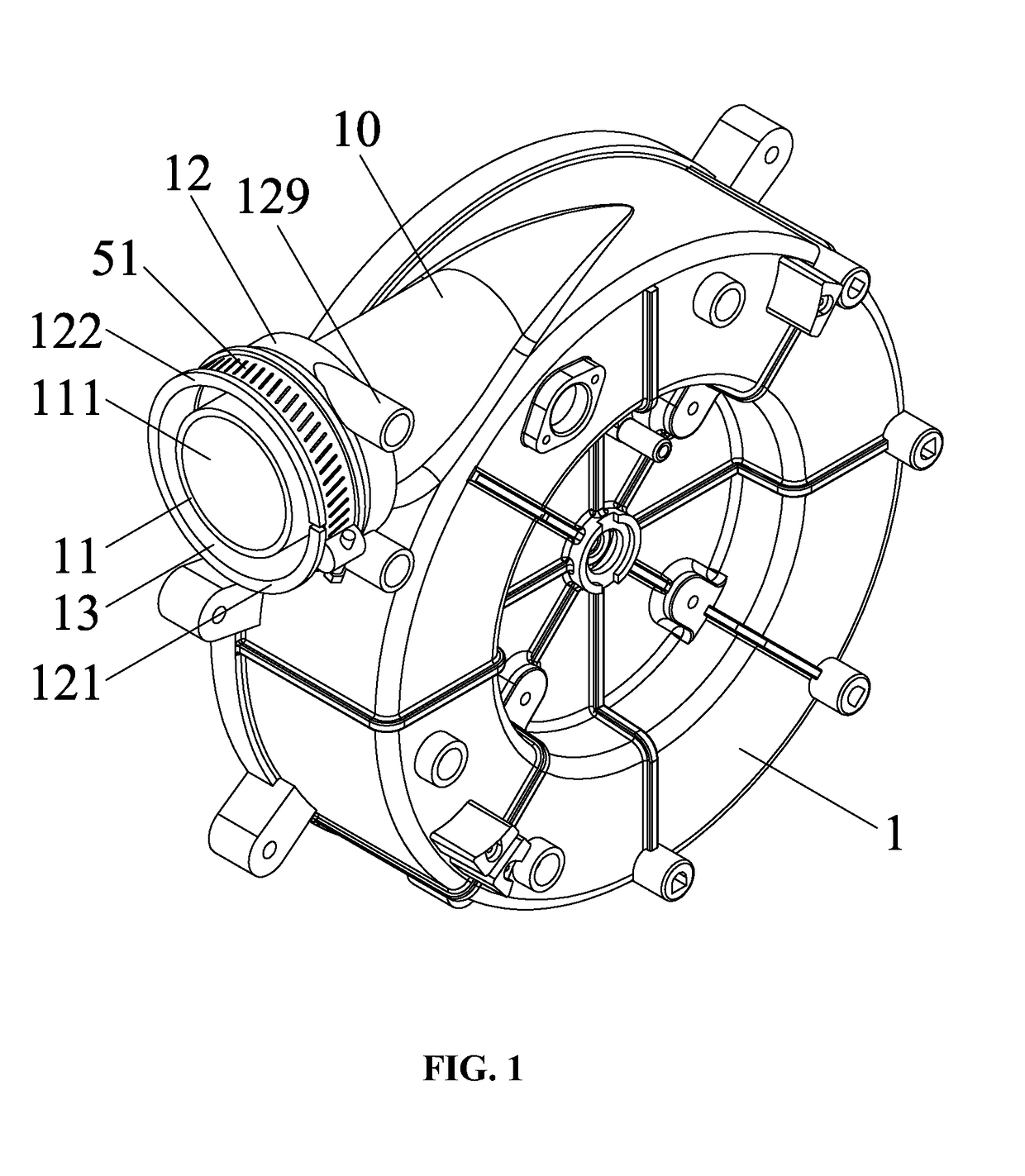
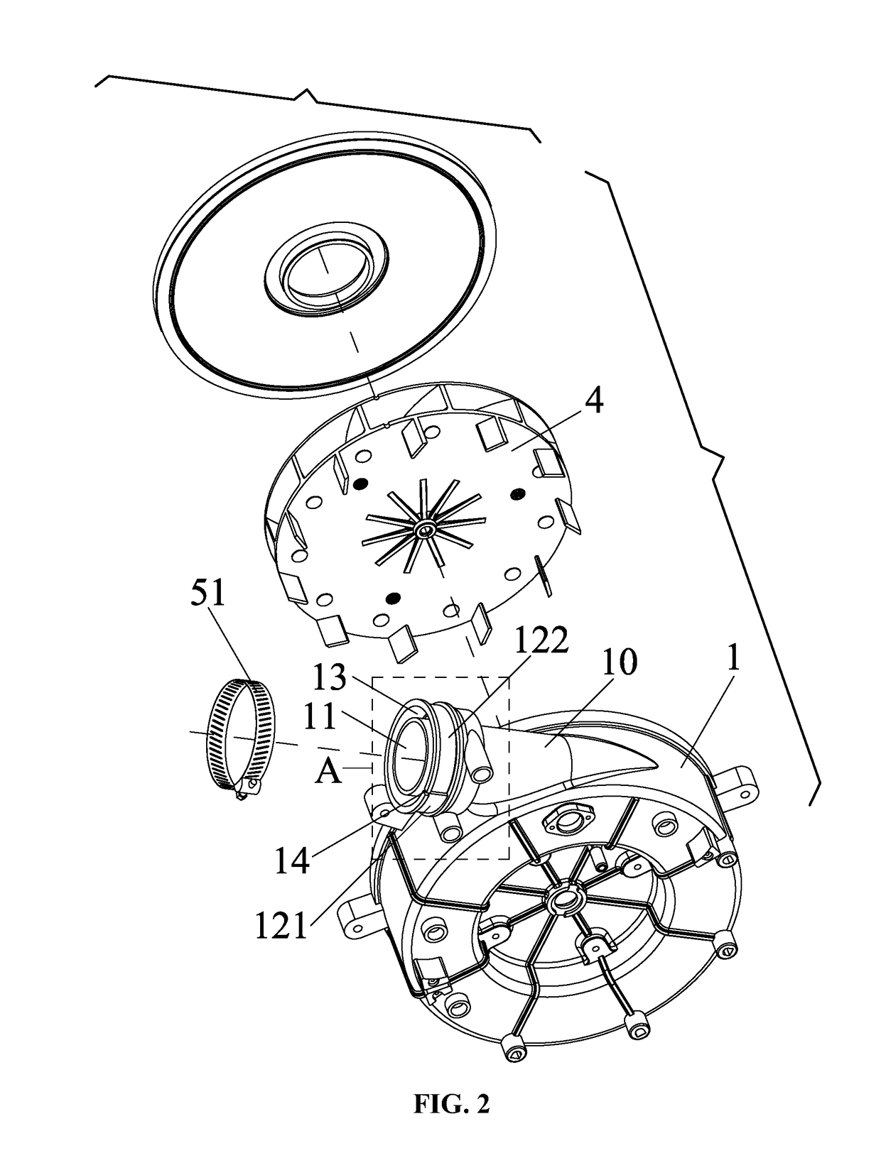
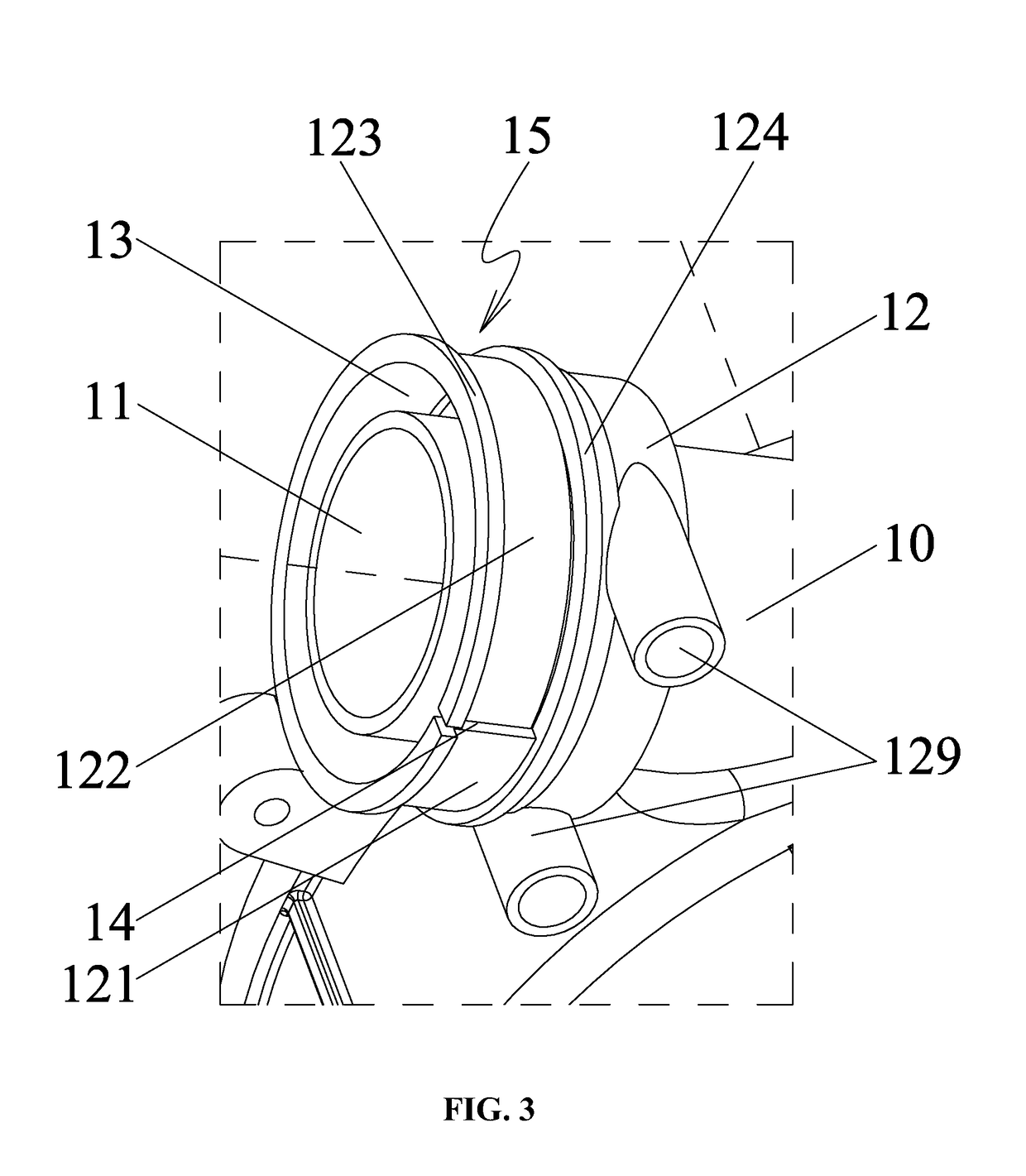
[0037]As shown in FIGS. 1-6, an induced draft fan comprises a volute 1 comprising a chamber 19, and a wind wheel 4 disposed in the chamber 19 of the volute 1. The wind wheel 4 is connected to and operationally driven by a rotation shaft of a motor. The motor is disposed in or out of the volute. An air discharge pipe 10 is disposed on one side of the volute, and comprises an inner pipe 11 and an outer pipe 12 surrounding the inner pipe 11. The inner pipe 11 of the air discharge pipe communicates with the chamber 19, to form an air discharge passage 111 of the induced drat fan. An annular groove 13 is disposed between the inner pipe 11 and the outer pipe 12. An outer end of the outer pipe 12 is provided with a curved groove 14, the curved groove 14 extends axially and circumferentially to divide the outer pipe 12 into a fixed part 121 and a flexible part 122.
[0038]The arrangement of the curved groove 14 increases the range of motion of the flexible part 122 along the circumferential d...
example 2
[0046]As shown in FIGS. 7-9, a gas furnace comprises an induced draft fan in Example 1 and a conversion interface 2 which is disposed on the air discharge pipe of the induced draft fan. The conversion interface 2 is embedded in the annular groove 13, a seal ring 3 is disposed between the conversion interface 2 and the outer pipe 12; the curved groove 14 is located outside the seal ring 3, a hose clamp 51 is disposed in the locating slot 15, the body of the hose clamp 51 is located on the flexible part 122 and the fixed part 121 to close up the curved groove.
[0047]When the conversion interface 2 is embedded in the annular groove 13, a discharge chamber 131 is formed between the inner wall of the conversion interface 2 and the inner pipe 11. The discharge chamber 131 communicates with the air discharge passage 111. The drain hole 128 communicates with the discharge chamber 131. During work, the rotation of the wind wheel 4 of the induced draft fan produces air flow, the air flows from...
example 3
[0048]FIGS. 10-13 show another induced draft fan which is different from that in Example 1 in that:
[0049]The curved groove 14 is L-shaped and comprises an axial part 141 and a circumferential part 142; the fixed part 121 comprises a lower lug 125 in the vicinity of the axial part 141, and the flexible part 122 comprises an upper lug 126 in the vicinity of the axial part 141 and corresponding to the lower lug 125; the upper lug 126 and the lower lug 125 each comprise mounting through holes 127, each mounting through hole 127 comprises a bolt 52, and a nut 53 is provided at a tail of the bolt 52, and the bolt 52 and the nut 53 cooperate to lock the fixed part 121 and the flexible part 122.
[0050]In this example, the lower lug and the upper lug are locked by the bolt and the nut, thus simplifying the structure, facilitating the assembly, and reducing the costs.
PUM
 Abstract
Description
Claims
Application Information
 - R&D
- Intellectual Property
- Life Sciences
- Materials
- Tech Scout
- Unparalleled Data Quality
- Higher Quality Content
- 60% Fewer Hallucinations
Browse by: Latest US Patents, China's latest patents, Technical Efficacy Thesaurus, Application Domain, Technology Topic, Popular Technical Reports.
© 2025 PatSnap. All rights reserved.Legal|Privacy policy|Modern Slavery Act Transparency Statement|Sitemap|About US| Contact US: help@patsnap.com


