
Locking device with embedded circuit board

a technology of embedded circuits and locking devices, which is applied in the direction of laminating printed circuit boards, alarms using electric shocks, and electric apparatus casings/cabinets/drawers, etc., can solve the problems of difficult and burdensome wiring, conventional electronic actuation, and inconvenient wiring into and through locks, so as to achieve easy and efficient electrification, increase performance capabilities, and facilitate and efficiently electrify

Active Publication Date: 2012-12-04
SARGENT MANUFACTURING CO INC
View PDF33 Cites 59 Cited by
  • Summary
  • Abstract
  • Description
  • Claims
  • Application Information

AI Technical Summary

Benefits of technology

[0016]A further object of the invention is to provide methods and apparatus for easily and efficiently electrifying existing access-control technology (e.g., an existing mechanical lock) having constrained real estate.
[0017]Still another object of the invention is to provide methods and apparatus for easily and efficiently providing existing access-control technology (e.g., an existing mechanical lock) with increased performance capabilities by securing a printed circuit board within the mechanical lock housing.
[0018]It is another object of the present invention to provide a unified design that allows for alternate circuit boards to be developed, which accomplishes different functions (i.e. modularity and future-proofing).
[0019]Another object of the present invention is to provide methods and apparatus for electrifying existing access-control technology (e.g., an existing mechanical lock) easily, efficiently and cost effectively.

Problems solved by technology

In both of these types of assemblies, since the electronic circuitry is external to the lock itself, intricate wiring is required to provide the necessary electrical connection between the external circuitry and the lock device.
Whether the electronic circuitry resides in a mortised recess or an escutcheon, it has been found that there are many disadvantages to these conventional electronically actuated lock assemblies.
With the constrained real estate in a majority of currently available locks, it has become difficult and burdensome to provide the necessary wiring into and throughout the lock for the electrical connection between the switches and actuators in the lock and the electronic circuitry external to the lock.
Concerns are also raised when too much electrical wiring resides external to the locking device.
Insulated wire harnesses routed through a lockbody are subject to damage from contact with mechanical components.
It is also undesirably burdensome, time consuming, expensive and expends valuable real estate within the lock by requiring the lock casing to be fabricated with a number of holes and slots for accommodating the inserted wiring, as well as to be fabricated with brackets or harnesses inside the lock for securing and positioning the wiring accommodated therein.
As such, these conventional mortised recess and escutcheon-type lock assemblies suffer from fabrication difficulties as well as performance limitations in providing accurate wire routing to switches, actuators, and wire harnesses within existing mechanical lock mechanisms having constrained real estate.
Additional drawbacks of housing electronics in an escutcheon is that these types of assemblies reside on and project outward from the exterior of the door, often precluding the addition of auxiliary hardware on such door.
Further drawbacks of the mortised recessed housed electronics include the increased difficulty for door manufacturers and installers to provide the precise sizing and shape of the mortised recess that fits the housing in which the electronics reside.

Method used


Image

  • Locking device with embedded circuit board
  • Locking device with embedded circuit board
  • Locking device with embedded circuit board

Examples


Embodiment Construction

)

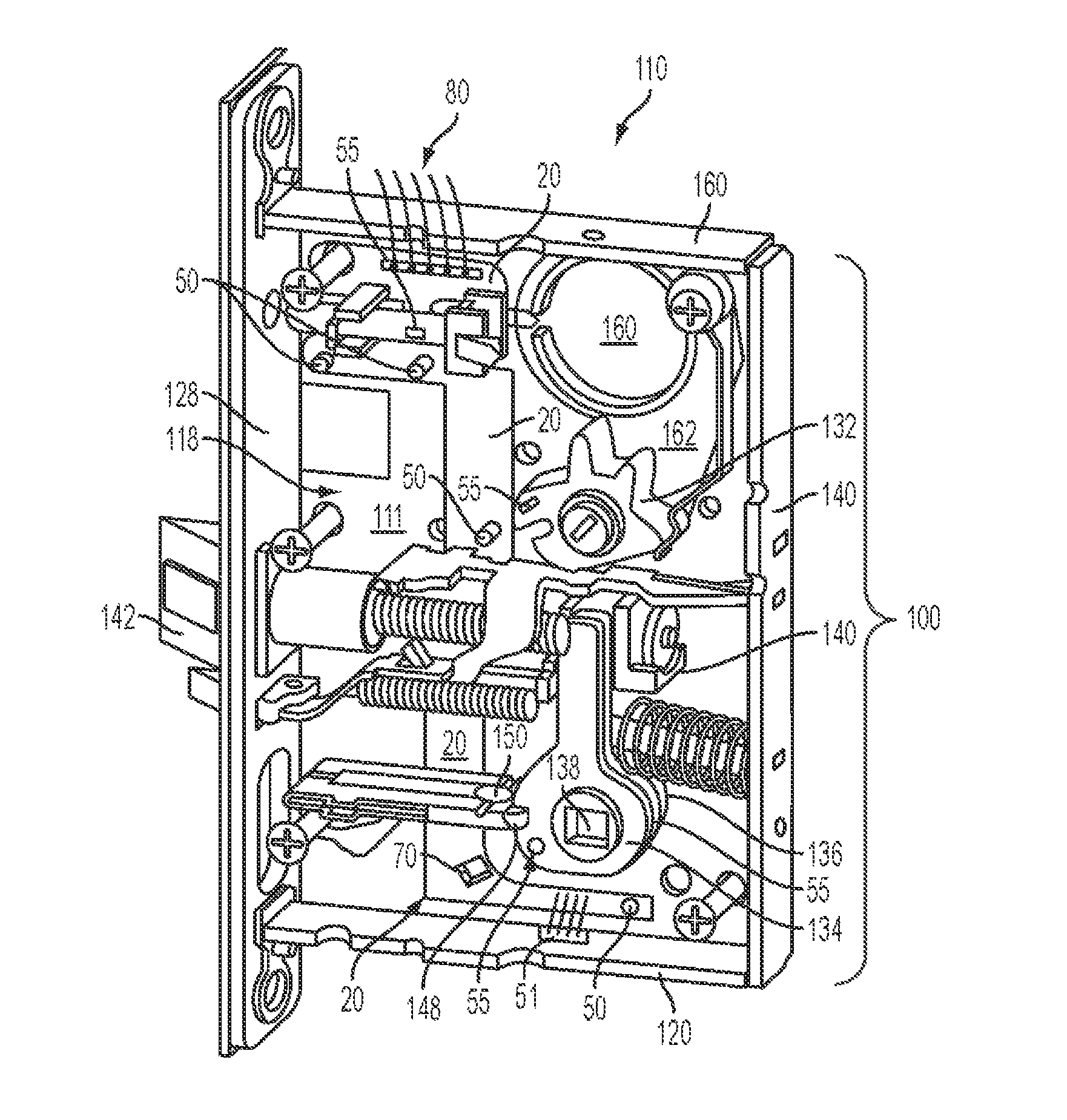
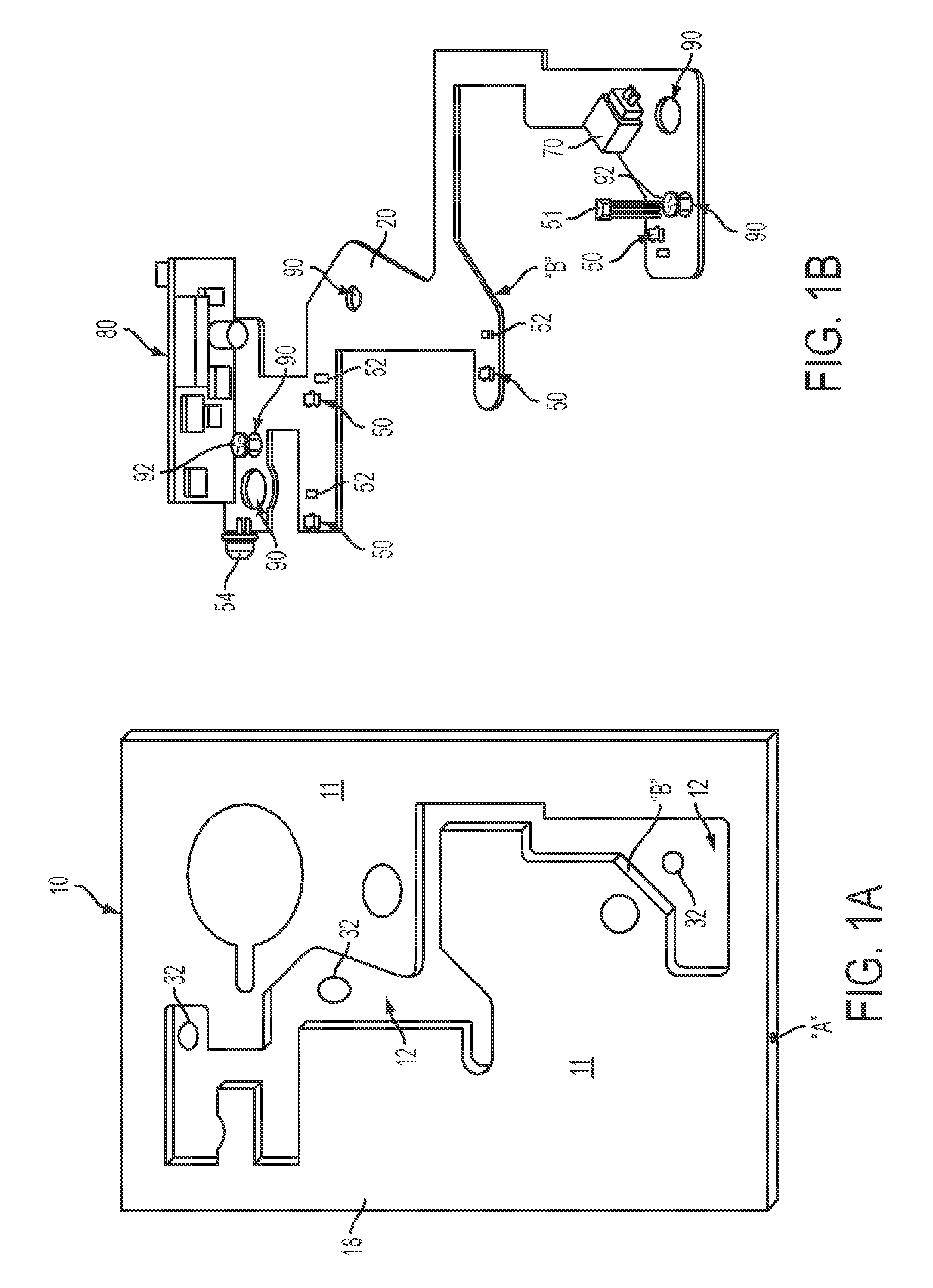
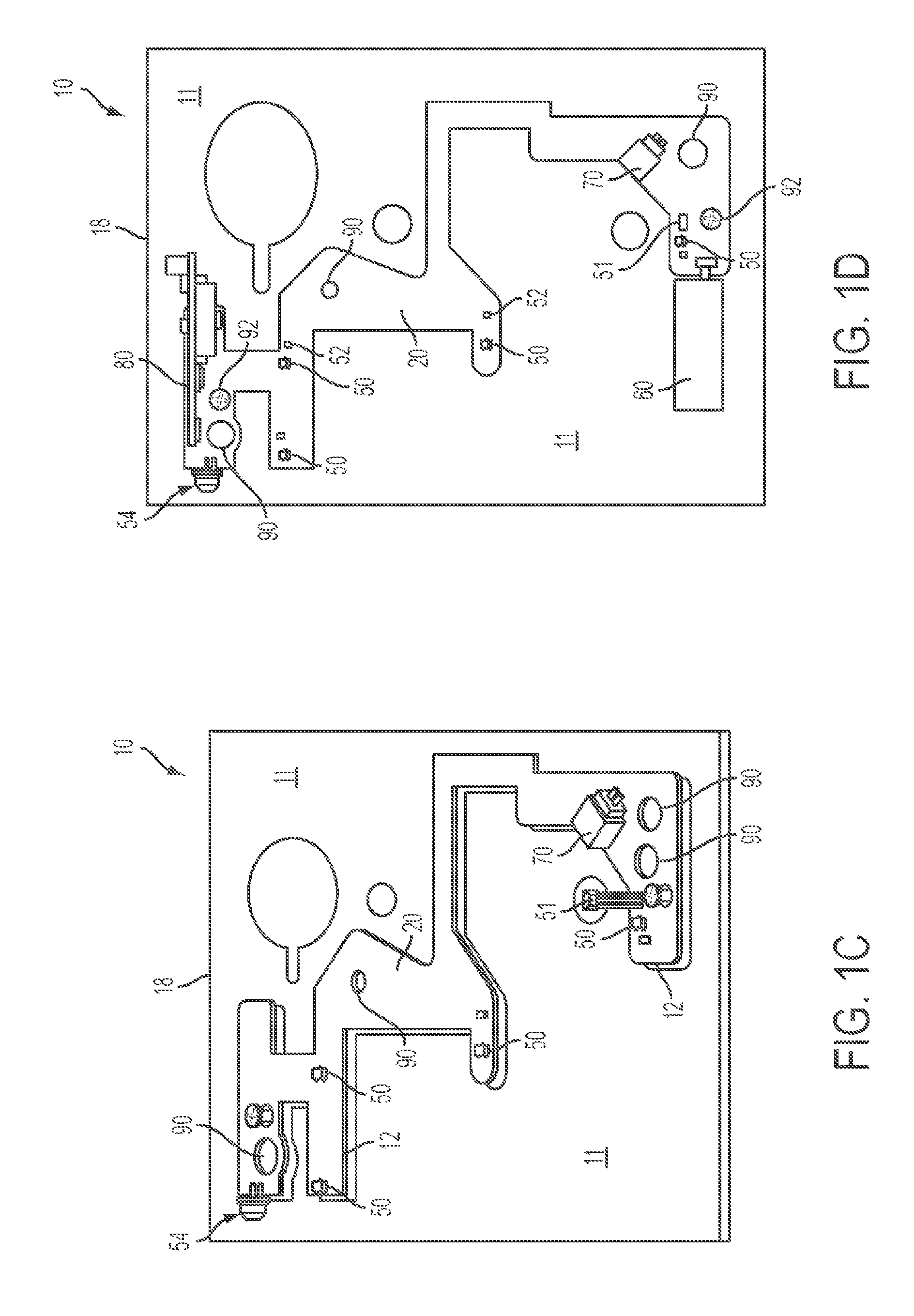
[0039]In describing the embodiments of the present invention, reference will be made herein to FIGS. 1A-3C of the drawings in which like numerals refer to like features of the invention.

[0040]In one or more embodiments, the invention integrates electronic circuitry within existing and future locking devices. The locking devices suitable for use include those housed either entirely or partially within a housing, wherein one or more electronic circuit boards may be embedded in accordance with the various embodiments of the invention. These locking devices include, but are not limited to, a mortise lock, a bored lock, a cylindrical lock, an electric strike, a tubular lock, an auxiliary lock, and a deadbolt and the like.

[0041]Referring to FIGS. 1A-F, at least one interior surface 11, 13 of a locking device housing 10 is provided with a channel 12 that corresponds to the shape, size and thickness of a corresponding printed circuit board (PCB) 20. In one or more embodiments, this channel...


PUM

PropertyMeasurementUnit
surface areaaaaaaaaaaa
electricalaaaaaaaaaa
shapeaaaaaaaaaa

Abstract

Electrified access-control technology devices for a door, particularly electrified locks for a door, having embedded circuitry therein, and methods of making the same. One or more printed circuit boards (PCBs) having various electronic circuitry are secured inside a housing that encases an access-control device, particularly a lock, for a door. The one or more PCB(s) may be embedded on an internal surface of the housing such that the embedded PCB resides inside the housing along with the lock itself. The embedded PCB(s) avoid interference of both any working components of the lock inside the housing and any openings residing in the housing.

Description

BACKGROUND OF THE INVENTION[0001]1. Field of the Invention[0002]This invention relates generally to embedded circuitry, and more particularly, to circuit boards embedded inside an access-control technology device of a door to provide electrification thereto.[0003]2. Description of Related Art[0004]There are currently various types of access-control technology devices available for use with, on or inside a door. For instance, it is known to use access-control technology in locking devices. In recent years, access-control technology in locking devices has increasingly shifted from traditional keying systems and mechanical articulation to digital monitoring and electronic actuation. Various electronically actuated locks and exit devices for doors exist in the art. These electronically actuated locks are generally classified into two categories, namely, those having electronic circuitry housed inside a mortised recess of a door, and those having electronic circuitry housed in an escutch...

Claims


Application Information

Patent Timeline
Patent Type & Authority Patents(United States)
IPC IPC(8): E05B45/06
CPCE05B9/02E05B17/22E05B47/00Y10T29/49124H05K3/0058E05B15/10Y10T292/1021Y10T70/5155Y10T70/7062Y10T29/49126Y10T292/102H05K13/00E05B47/0046E05B2047/0048E05B2047/0072H05K7/1427H05K13/04E05B47/0012E05B63/08G08B15/005
Inventor PICARD, DANIEL J.HUNT, ROBERT C.LOWDER, SCOTT B.
Owner SARGENT MANUFACTURING CO INC
Learn More