Locking device with configurable electrical connector key and internal circuit board for electronic door locks

a technology of configurable electrical connectors and electronic door locks, which is applied in the direction of laminating printed circuit boards, burglar alarms with fastening tampering, instruments, etc., can solve the problems of difficult and burdensome to provide the necessary wiring into and through the lock, difficult and efficient electrification, and easy and efficient operation. , to achieve the effect of easy and efficient electrification

Active Publication Date: 2017-01-26
SARGENT MANUFACTURING CO INC
View PDF4 Cites 10 Cited by
  • Summary
  • Abstract
  • Description
  • Claims
  • Application Information

AI Technical Summary

Benefits of technology

[0022]A further object of the invention is to provide methods and apparatus for easily and efficiently electrifying existing access-control technology (e.g., an existing mechanical lock) having constrained real estate.
[0023]Still another object of the invention is to provide methods and apparatus for easily and efficiently providing existing access-control technology (e.g., an existing mechanical lock) with increased performance capabilities by securing a printed circuit board within the mechanical lock housing.
[0024]It is another object of the present invention to provide a unified design that allows for alternate circuit boards to be developed, which accomplishes different functions (i.e. modularity and future-proofing).
[0025]Another object of the present invention is to provide methods and apparatus for electrifying existing access-control technology (e.g., an existing mechanical lock) easily, efficiently and cost effectively.

Problems solved by technology

Problems arise in making multiple connections between the electronic door lock components and an external control unit.
Such problems also encompass the connectors, the wiring harness and the selection of sensors within the lock that are to be made available to the external control unit.
This is labor intensive and expensive as well as making it difficult to keep the many variations in stock for rapid delivery to customers.
Due to constrained real estate in a majority of currently available locks, it has also become difficult and burdensome to provide the necessary wiring into and throughout the lock for the electrical connection between the switches, sensors and actuators in the lock and the electronic circuitry external to the lock.
Concerns are also raised when too much electrical wiring resides external to the locking device.
Insulated wire harnesses routed through a lockbody are subject to damage from contact with mechanical components.
It is also undesirably burdensome, time consuming, expensive and expends valuable real estate within the lock by requiring the lock casing to be fabricated with a number of holes and slots for accommodating the inserted wiring, as well as to be fabricated with brackets or harnesses inside the lock for securing and positioning the wiring accommodated therein.
As such, these conventional mortised recess and escutcheon-type lock assemblies suffer from fabrication difficulties as well as performance limitations in providing accurate wire routing to switches, actuators, and wire harnesses within existing mechanical lock mechanisms having constrained real estate.

Method used


Image

  • Locking device with configurable electrical connector key and internal circuit board for electronic door locks
  • Locking device with configurable electrical connector key and internal circuit board for electronic door locks
  • Locking device with configurable electrical connector key and internal circuit board for electronic door locks

Examples


Embodiment Construction

)

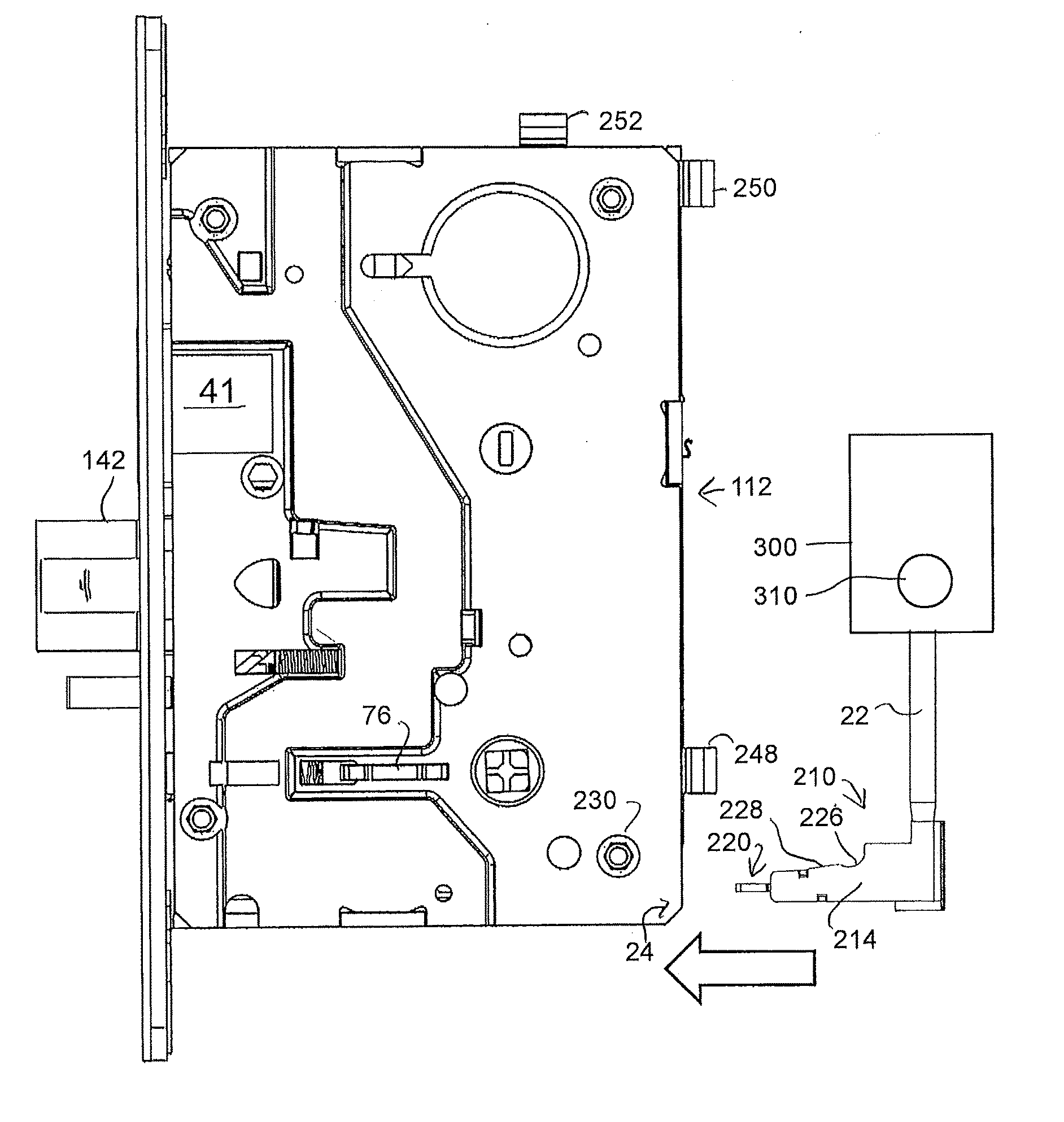
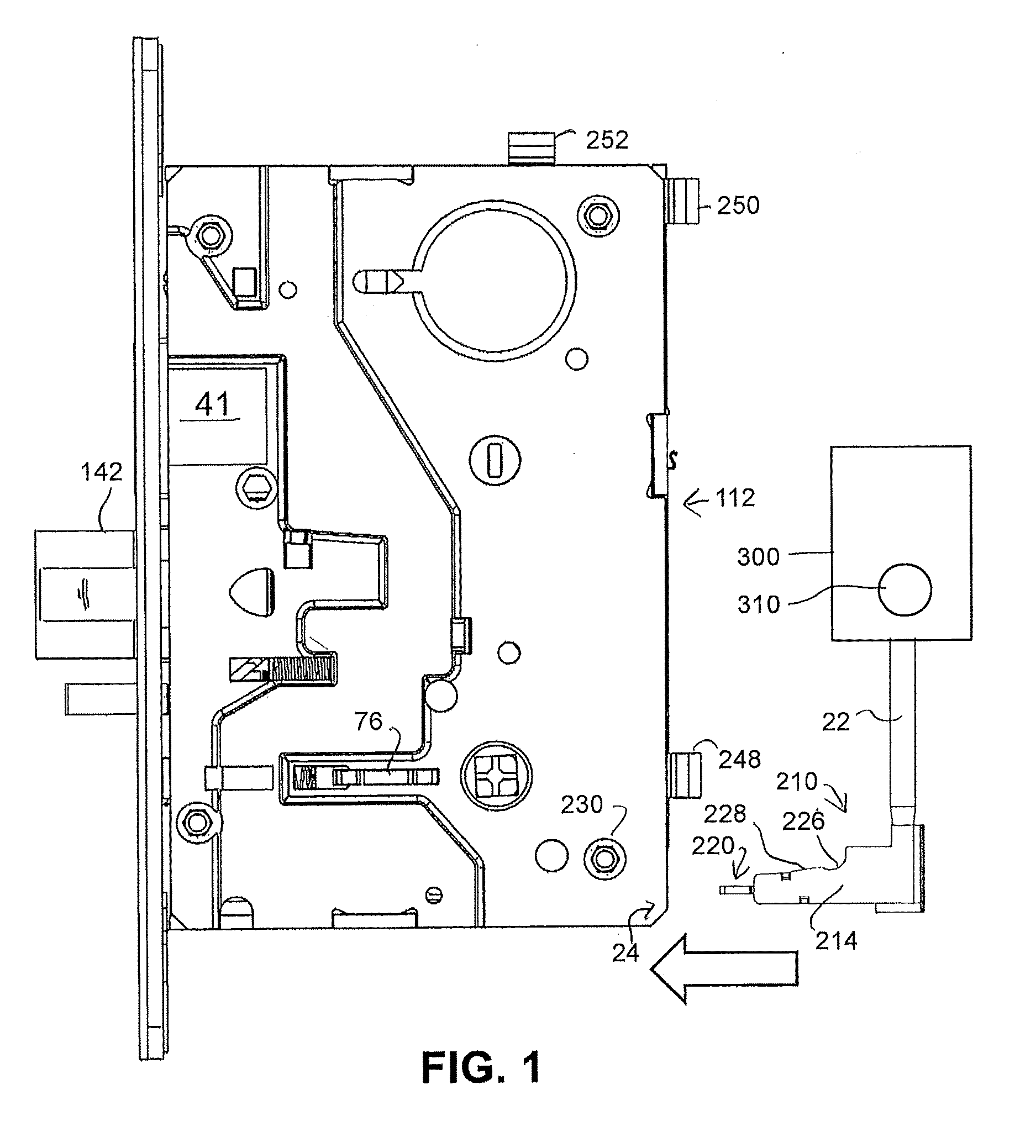
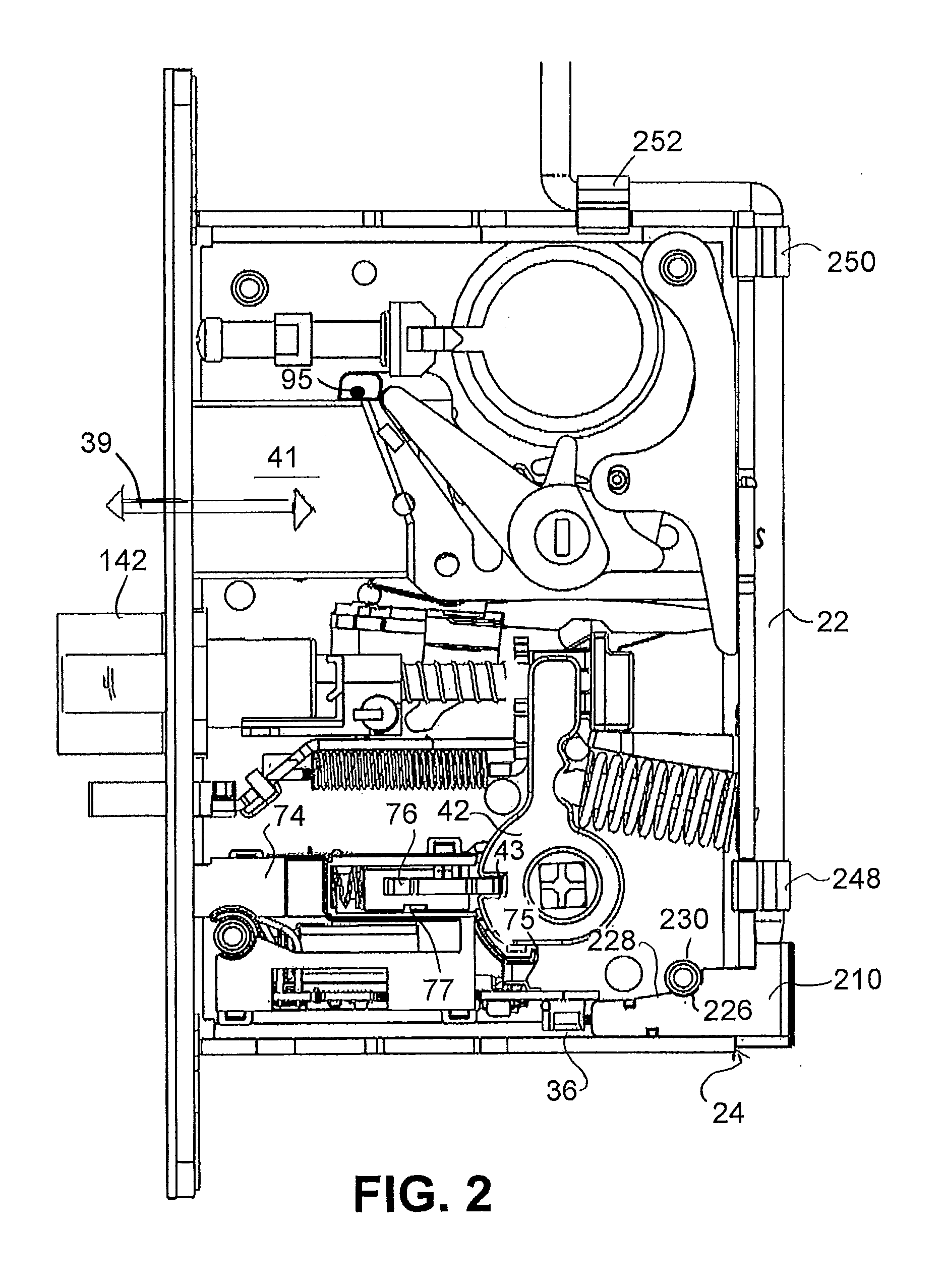
[0084]In describing the embodiments of the present invention, reference will be made herein to FIGS. 1-12C of the drawings in which like numerals refer to like features of the invention.

[0085]In one or more embodiments, the invention integrates electronic circuitry within existing and future locking devices. The locking devices suitable for use include those housed either entirely or partially within a housing, wherein one or more electronic circuit boards may be embedded in accordance with the various embodiments of the invention. These locking devices include, but are not limited to, a mortise lock, a bored lock, a cylindrical lock, an electric strike, a tubular lock, an auxiliary lock, and a deadbolt and the like. The “electronic lock” as referred to herein contains one or more mechanical locking components which may be a latchbolt, a dead bolt, a guard bolt, handles for retracting the latchbolt (or lock components connected to such handles), knobs or levers for extending / retrac...


PUM

PropertyMeasurementUnit
period of timeaaaaaaaaaa
electricalaaaaaaaaaa
poweraaaaaaaaaa

Abstract

Locks, systems and methods of monitoring a lock, the lock having a hub with a slot rotatable by a handle to open and close a latchbolt. A locking member is moveable into and out of engagement with the hub slot to prevent and permit movement of the hub and latchbolt. A sensor on the lock, adjacent the hub and locking member, monitors a moving lock component. The sensor may sense the position of the locking member in or out of engagement with the hub slot. The sensor may be a reed switch actuated by a magnet on the moving lock component. The lock may further include a magnet mounted on the hub and the sensor may comprise a reed switch capable of being actuated by the magnet on the hub. The lock and system may include an external control unit having an alarm for controlling operation of the lock.

Description

RELATED APPLICATIONS[0001]This application is a divisional application of U.S. patent application Ser. No. 14 / 622,200 filed on Feb. 13, 2015, which is a continuation-in-part of U.S. patent application Ser. No. 14 / 565,813 filed on Dec. 10, 2014, which is a divisional application of U.S. patent application Ser. No. 13 / 600,353 filed on Aug. 31, 2012, now U.S. Pat. No. 8,922,370, which is a continuation of U.S. patent application Ser. No. 12 / 712,643, filed on Feb. 25, 2010, now U.S. Pat. No. 8,325,039. U.S. patent application Ser. No. 14 / 622,200 is also a continuation-in-part of PCT Application No. PCT / US2014 / 027109 filed on Mar. 14, 2014, which claims the benefit of U.S. provisional patent application No. 61 / 791,975 filed on Mar. 15, 2013.BACKGROUND OF THE INVENTION[0002]1. Field of the Invention[0003]The present invention relates to devices for making electrical connections to electrical components within electronic door locks. More specifically, the present invention relates to a sha...

Claims


Application Information

Patent Timeline
Patent Type & Authority Applications(United States)
IPC IPC(8): E05B45/06E05B9/02E05B17/22H05K7/14E05B17/20E05B55/00G07C9/00E05B63/08E05B47/00
CPCE05B45/06E05B2045/0665E05B9/02E05B17/22E05B47/0001E05B17/2084E05B55/00G07C9/00658H05K7/1418E05B2045/065E05B2047/0069E05B2047/0073E05B2047/0076E05B2045/0695E05B2045/064E05B63/08E05B15/10E05B47/00E05B47/0012E05B63/0065E05B2047/0068G08B13/06H05K3/0058Y10T29/49124Y10T29/49126Y10T70/5155Y10T70/7062Y10T292/102Y10T292/1021E05B2047/0084G07C9/00714G08B15/005
Inventor LOWDER, SCOTT B.
Owner SARGENT MANUFACTURING CO INC
Why Eureka
Try Eureka