Automatic charge hearth access door assembly

a technology of access door and automatic charge, which is applied in the direction of furnace doors, lighting and heating apparatus, furnaces, etc., can solve the problems of rear plate heat loss and damag

Active Publication Date: 2015-06-18
HONDA MOTOR CO LTD
View PDF14 Cites 13 Cited by
  • Summary
  • Abstract
  • Description
  • Claims
  • Application Information

AI Technical Summary

Problems solved by technology

However, the typical operator cannot assert enough force to hold the door tightly closed resulting in heat loss and damage of the rear plate.

Method used


Image

  • Automatic charge hearth access door assembly
  • Automatic charge hearth access door assembly
  • Automatic charge hearth access door assembly

Examples


Embodiment Construction

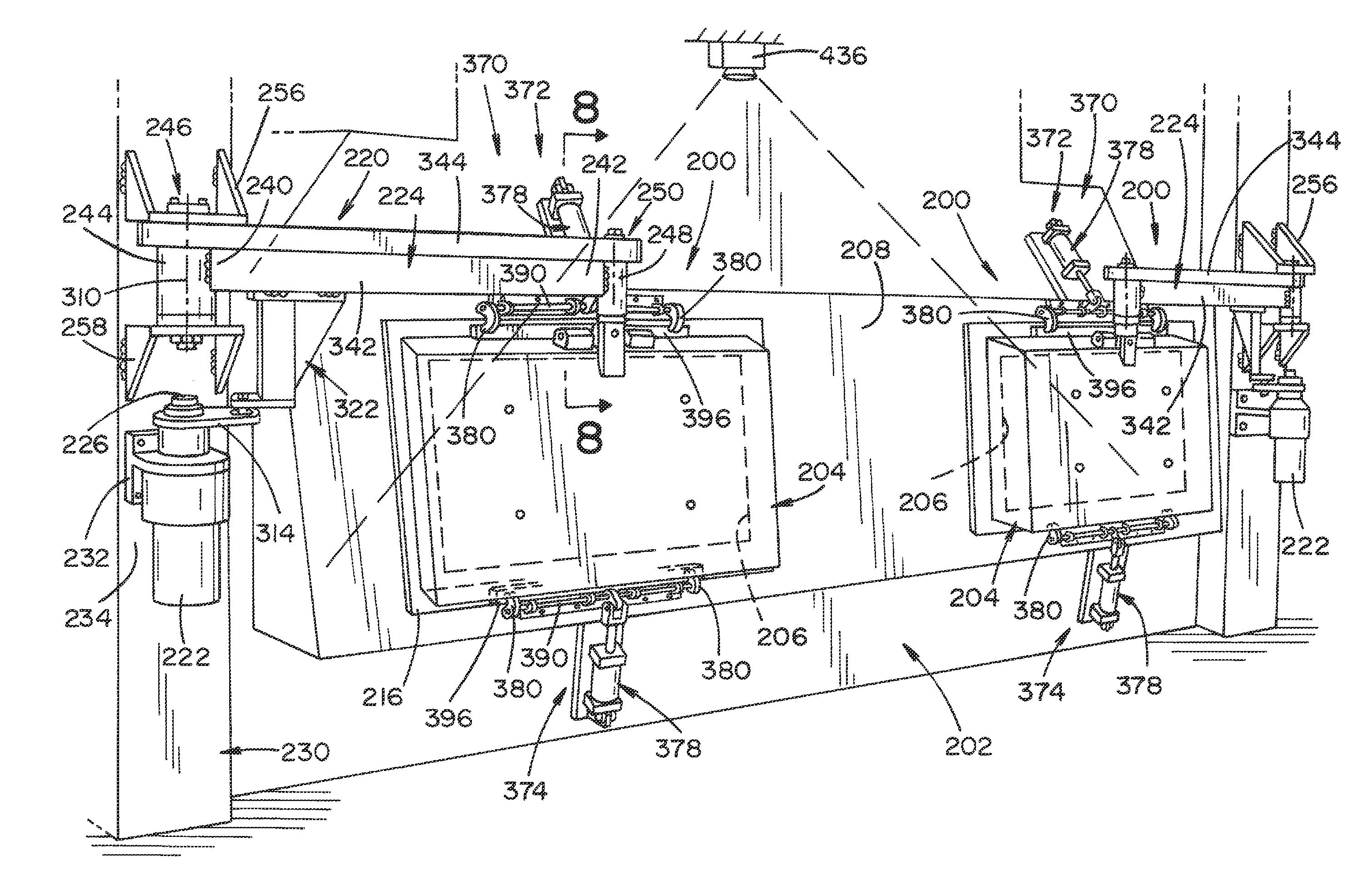
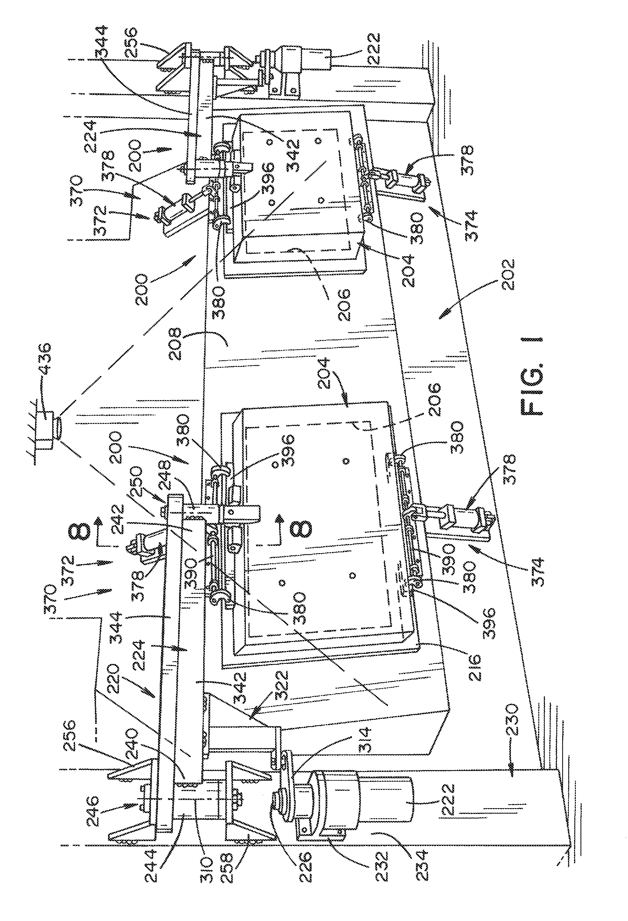
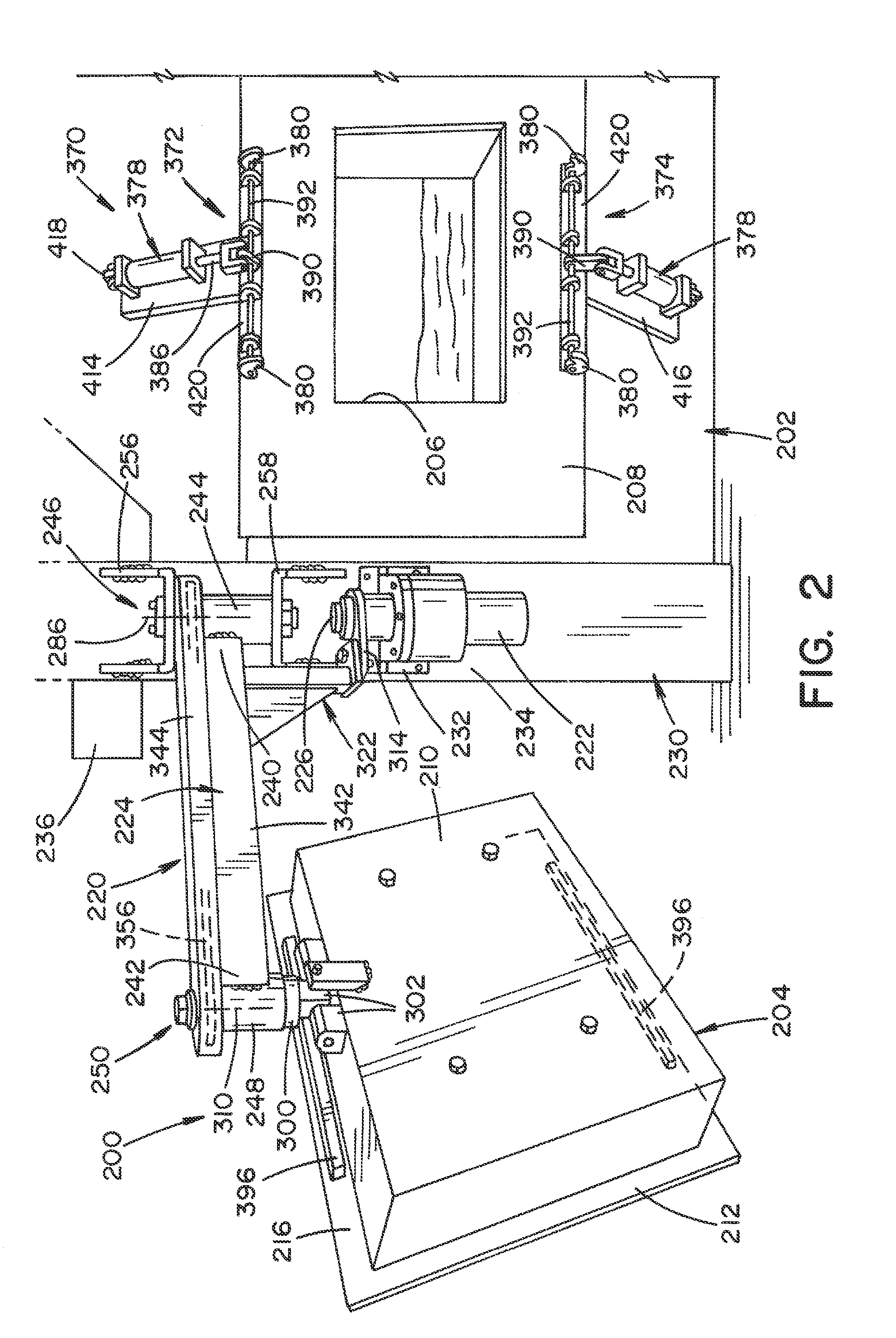
[0014]It should, of course, be understood that the description and drawings herein are merely illustrative and that various modifications and changes can be made in the structures disclosed without departing from the present disclosure. In general, the figures of the exemplary automatic charge hearth access door assembly are not to scale. It will also be appreciated that the various identified components of the exemplary automatic charge hearth access door assembly disclosed herein are merely terms of art that may vary from one manufacturer to another and should not be deemed to limit the present disclosure.

[0015]Referring now to the drawings, wherein like numerals refer to like parts throughout the several views, FIG. 10 illustrates a known hearth access door assembly 100 for a melting furnace 102. The assembly 100 includes an access door 104 movable between a closed position for covering a furnace opening (not shown) located on a face 106 of the furnace 102 and an opened position ...


PUM


Abstract

An automatic charge hearth access door assembly for a melting furnace includes an access door movable between a closed position for covering a furnace opening located on a face of the furnace and an opened position for providing access to the furnace opening. A latch mechanism is configured to automatically secure the access door to the face of the furnace in the closed position. An open-and-close drive assembly includes a motor and arm operably connected to the motor. The open-and-close drive assembly is configured to automatically move the access door relative to the face of the furnace between the closed position and opened position and simultaneously move the access door relative to the arm.

Description

BACKGROUND[0001]Melting furnaces in die cast are used to melt aluminum to produce engine block and head castings. The furnaces have a front door and back access doors to clean the refractory and remove impurities from the aluminum. The front door typically has an automatic lift hoist to open and close the door, but the rear access doors are generally opened, closed, clamped and unclamped manually. The normal push / pull force, as designed by the furnace manufacturer, is about 60 pounds per door based on performed measurements. There is also pushing and pull forces attributed to the manual locking clamps. However, the typical operator cannot assert enough force to hold the door tightly closed resulting in heat loss and damage of the rear plate. Further, for safety concerns, there is a need to prevent the operator from physically contacting the door to open it and to prevent the operator from being in the general area of the furnace while the rear access doors are opening.BRIEF DESCRIPT...

Claims


Application Information

Patent Timeline
Patent Type & Authority Applications(United States)
IPC IPC(8): F27D1/18F27D21/00
CPCF27D1/1858F27D2021/0057F27D21/00F27D1/1866F27D19/00F27D2001/1875F27D2019/0084
Inventor TRENT, JR., KEVIN D.TEETS, JOHNROBERT J.MERRICLE, PATRICK A.FELL, LYNN
Owner HONDA MOTOR CO LTD
Why Eureka
Try Eureka