Gimbaled ceiling lamp

Active Publication Date: 2015-06-25
3336820 NOVA SCOTIA LTD +1
View PDF6 Cites 1 Cited by
  • Summary
  • Abstract
  • Description
  • Claims
  • Application Information

AI Technical Summary

Benefits of technology

The patent describes a ceiling lamp that can be adjusted to face in different directions. It is supported by a ceiling component that includes a concave hemispherical framework that extends above a ceiling trim flange. The one or more LEDs are mounted on a board that is contained within a hemispherical housing. The housing is rotatably retained within the framework and may be rotated 360 degrees in the horizontal plane of the ceiling and within a vertical plane below the ceiling. The heat is dissipated through the housing that comprises a hemispherical heat sink, and that is supported within the framework by an adjustment screw. The adjustment screw is held by, and passes through, a concave adjustment plate above the circular ring positioned above the heat sink and LEDs. An adjustment nut on the adjustment screw, or some other adjustment mechanism, can tighten the heat sink against the framework, thereby creating a frictional interface that holds the heat sink and LED array in a desired orientation. The technical effect of this invention is that it allows for easy adjustment of the lamp housing in different directions by hand.

Problems solved by technology

Twisting or rotating the lamp may require removal of the trim or of the movable lamp housing, and may prove difficult or even impossible.
Such lighting may include halogen incandescent bulbs or light emitting diodes (LEDs) that may be gathered in an array to provide sufficient lighting for the purpose, and may require a heat sink to conduct excessive heat away from the lighting element.
While this arrangement may permit omnidirectional focusing of the LED array, it is a large and bulky structure that takes up significant space within the ceiling cavity and may not be suitable for limited space environments.

Method used


Image

  • Gimbaled ceiling lamp
  • Gimbaled ceiling lamp
  • Gimbaled ceiling lamp

Examples


Embodiment Construction

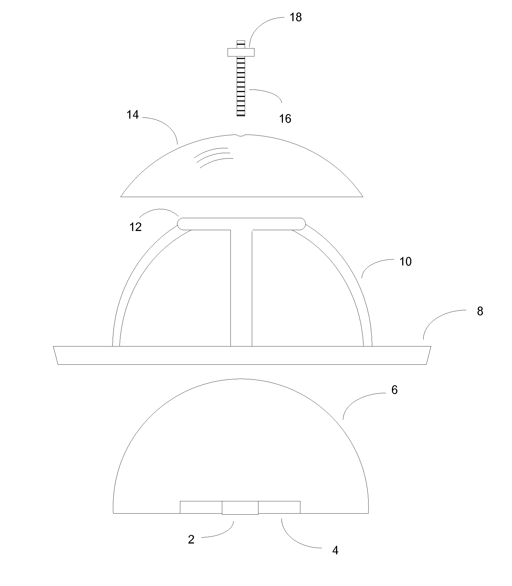
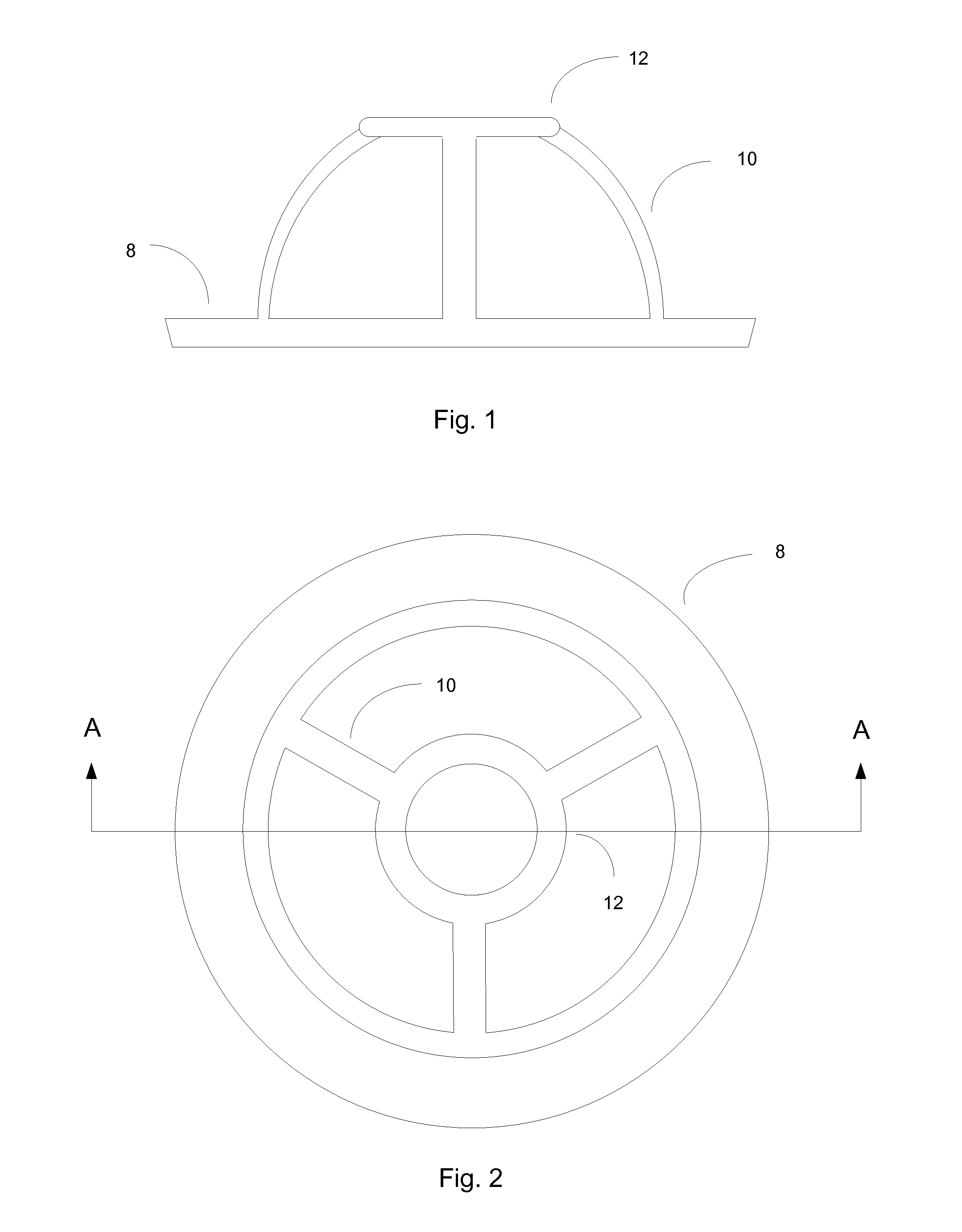
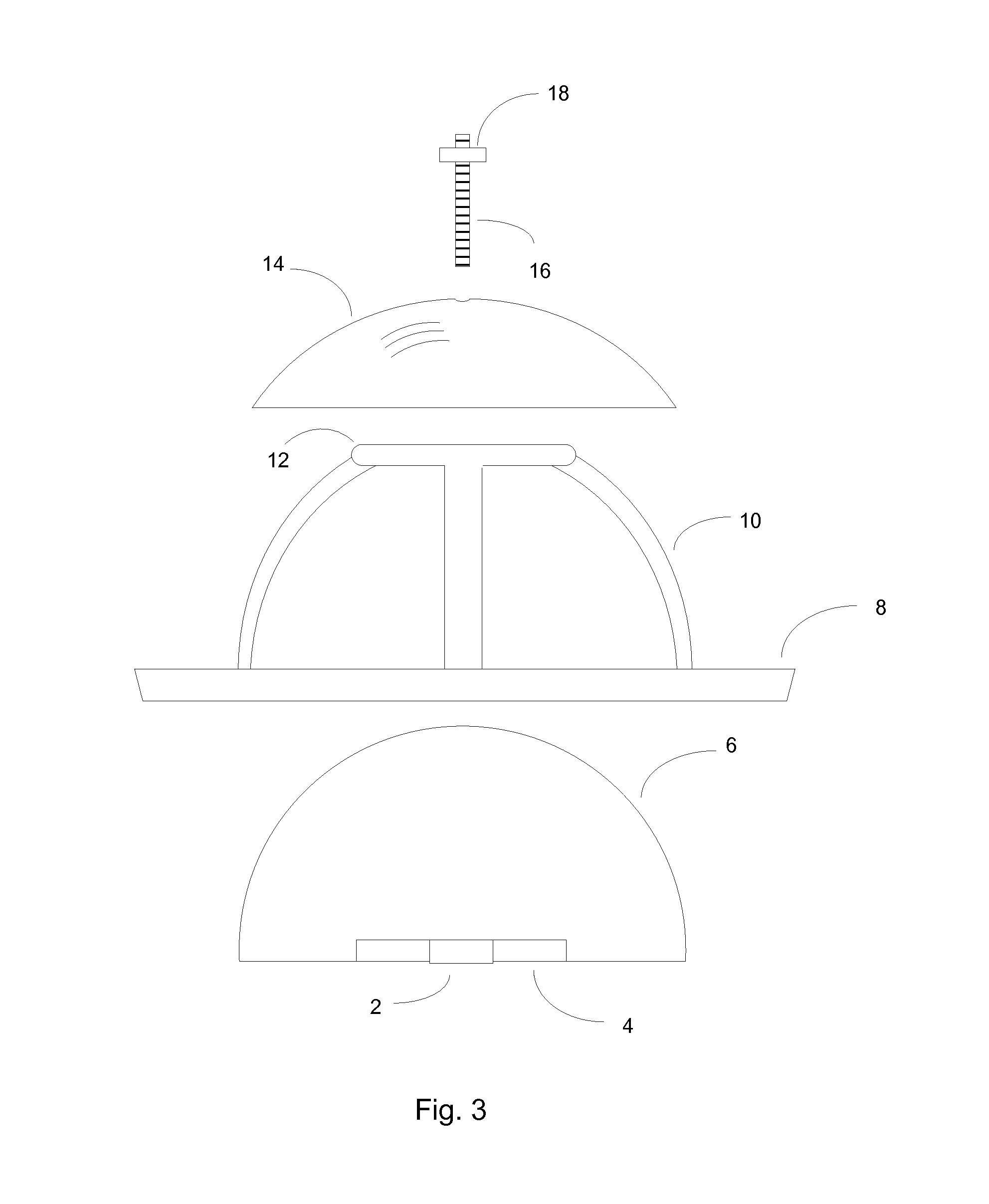
[0011]In FIG. 1, a ceiling component comprising a trim flange 8, a ring 12, and a framework 10, is shown in elevational view. The component fits into a ceiling cavity and the trim flange 8 remains below the cavity and is held against the ceiling. A framework 10 extends into the ceiling cavity. Attachment means (not shown) hold the trim flange 8 and framework 10, 12 within the cavity, and may be any well-known attachment mechanism.

[0012]FIG. 2 is a plan view of the trim flange 8 and framework having “legs”10 and a ring 12 centered above the ceiling cavity. Although FIG. 2 shows a framework having 3 legs, the framework need not be so limited and may have but a single leg, or a plurality of legs sufficient to hold the ring 12 and support the lamp housing.

[0013]FIG. 3 depicts a view of the gimbaled lamp in position to be assembled. The adjustment screw 16 and adjustment nut 18 extend through the adjustment plate 14, which is in the form of a concave disc. The concave disc 14 rests atop ...


PUM


Abstract

A ceiling lamp consists of one or more LEDs supported by a housing that fits within a hemispherical framework that may be installed in a ceiling. The LED housing comprises a hemispherical heat sink that may be movably retained within the framework and may be rotated 360 degrees in the horizontal plane and downwardly in the vertical plane. The frame has one or more upwardly extending legs rigidly attached to a ceiling trim and that hold a circular ring positioned above the heat sink. An adjustment screw passes through a concave disc above the ring, and extends through the ring where it is attached to the hemispherical heat sink.

Description

CROSS REFERENCE TO RELATED APPLICATIONS[0001]This application claims the benefit of U.S. Provisional Application Ser. No. 61 / 919,379 filed Dec. 20, 2013, the disclosure of which is hereby incorporated herein by reference in its entirety.BACKGROUND OF THE INVENTION[0002]Gimbaled ceiling lighting fixtures having a single plane of rotation are well known in the art. Such a gimbaled lamp consists of a fixed ceiling trim housing and a movable lamp housing in which the lamp housing will typically be supported on a horizontal axis attached to the ceiling trim, and passing through the approximate center of the lamp housing. In this configuration, the lamp housing may be rotated about the axis and is thereby able to be focused upon objects below the ceiling and within the plane of rotation. When it is desired to point the lamp at objects outside the plane of rotation, it may necessary to twist the ceiling trim housing within the ceiling cavity, or turn a rotatable element within the ceiling ...

Claims


Application Information

Patent Timeline
IPC IPC(8): F21S8/04F21V29/00F21K99/00
CPCF21S8/046F21K9/30F21V29/22F21V14/02F21W2131/30F21V17/06F21Y2101/02F21S8/026F21V21/30F21V29/70F21K9/20F21Y2115/10
Inventor SANTIAGO, DWIGHT D.HAUBACH, TIMOTHY J.
Owner 3336820 NOVA SCOTIA LTD
Why Eureka
Try Eureka