Method and apparatus for blending regions scanned by a beam scanner

US7002716B2Inactive Publication Date: 2006-02-21MICROVISION
27 Cites 17 Cited by

Patent Information

Authority / Receiving Office
US · United States
Current Assignee / Owner
Publication Date
2006-02-21
Estimated Expiration
Not applicable · inactive patent

Smart Images

  • Figure 1
    Figure 1
  • Figure 2
    Figure 2
  • Figure 3
    Figure 3
Patent Text Reader

Abstract

A beam scanner is operable to scan light in two or more axes, typically in a raster pattern that includes a fast scan axis and a slow scan axis. Plural beams of light are scanned, each beam of light producing a scanned region that at least partially overlaps at least one adjoining scanned region. Scanned regions may be aligned to adjoin and overlap along a dimension corresponding to the slow scan axis. The beam scanner may comprise a scanned beam display and / or a scanned beam image capture device. In a display, the power level of overlapping displayed pixels may be scaled to provide smooth transitions between adjoining regions to improve the image quality presented to a viewer. In an image capture device, one or more detectors is operable to collect light scattered from adjoining regions and a controller is operable to produce an image from the scanned regions.
Need to check novelty before this filing date? Find Prior Art

Description

[0001] This is a continuation of application Ser. No. 10 / 339,953, filed Jan. 10, 2003 now U.S. Pat. No. 6,687,034, which is a continuation of application Ser. No. 10 / 075,679, filed on Feb. 13, 2002 and issued as U.S. Pat. No. 6,512,622 on Jan. 28, 2003, which is a divisional of application Ser. No. 09 / 816,804, filed on Mar. 23, 2001 and issued as U.S. Pat. No. 6,384,406 on May 7, 2002, which is a continuation of application Ser. No. 09 / 370,795, filed on Aug. 5, 1999 and issued as U.S. Pat. No. 6,256,131 on Jul. 3, 2001.TECHNICAL FIELD

[0002] The present invention relates to scanned light devices and, more particularly, to scanned light beam displays and imaging devices for viewing or collecting images.BACKGROUND OF THE INVENTION

[0003] A variety of techniques are available for providing visual displays of graphical or video images to a user. In many applications cathode ray tube type displays (CRTs), such as televisions and computer monitors produce images for viewing. Such devices suffe...

Examples

Embodiment Construction

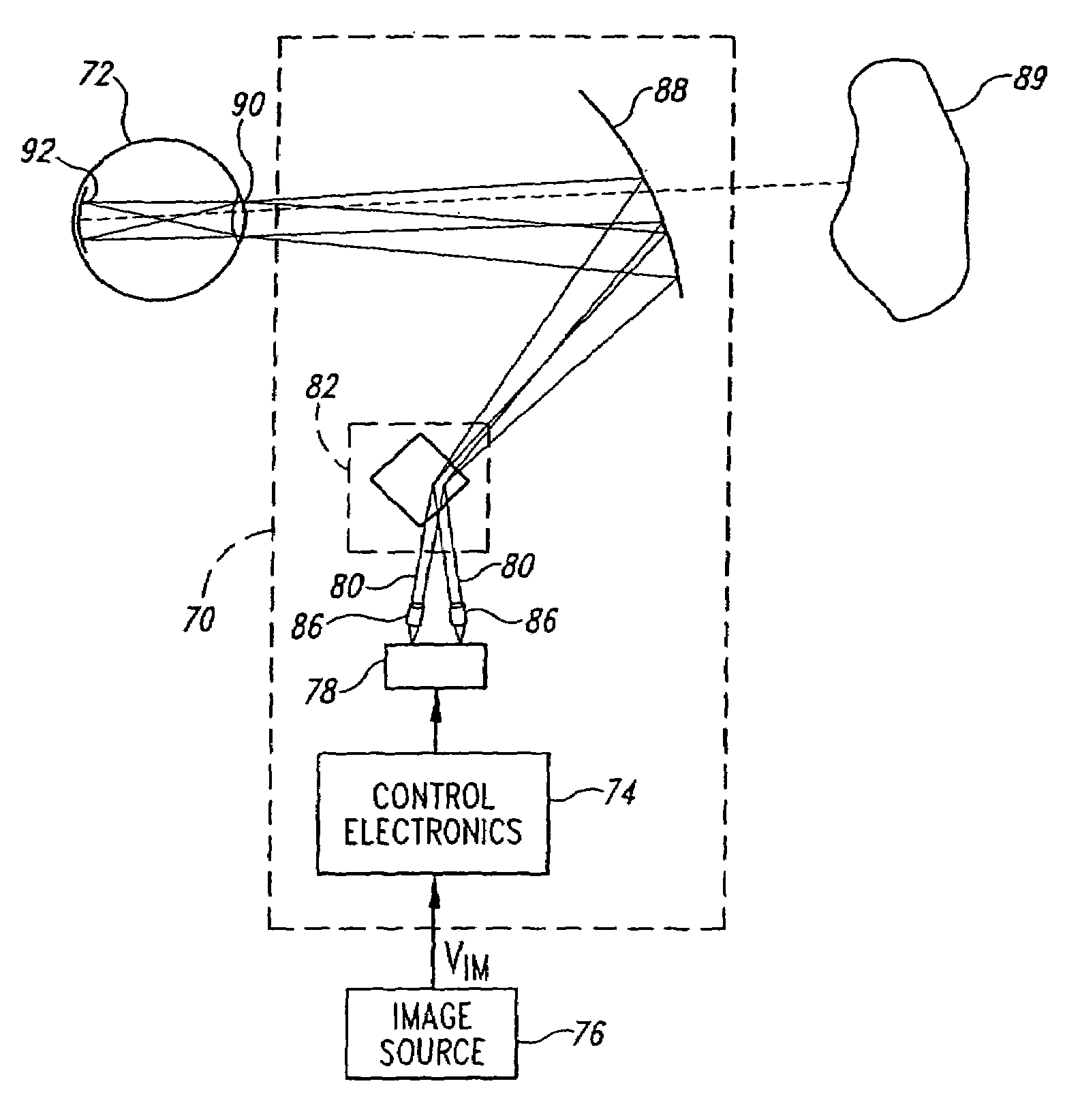
[0069]As shown in FIG. 6, a scanned beam display 70 according to one embodiment of the invention is positioned for viewing by a viewer's eye 72. While the display 70 is presented herein is scanning light into the eye 72, the structures and concepts described herein can also be applied to other types of displays, such as projection displays that include viewing screens.

[0070]The display 70 includes four principal portions, each of which will be described in greater detail below. First, control electronics 74 provide electrical signals that control operation of the display 70 in response to an image signal VIM from an image source 76, such as a computer, television receiver, videocassette player, DVD player, remote sensor, or similar device.

[0071]The second portion of the display 70 is a light source 78 that outputs modulated light beams 80, each having a modulation corresponding to information in the image signal VIM. The light source 78 may utilize coherent light emitters, such as l...