
Firefighter's appliance

a technology for firefighters and appliances, applied in the field of firefighter appliances, can solve the problems of significant liability to the effectiveness and/or safety of firefighters, poor functioning or non-functioning appliances or tools,

Active Publication Date: 2015-07-09
SOLLIDAY PAUL A
View PDF4 Cites 1 Cited by
  • Summary
  • Abstract
  • Description
  • Claims
  • Application Information

AI Technical Summary

Benefits of technology

The invention is a system for firefighters that provides air to a breathing device while also supplementing the air needed for the firefighter's tool, such as a chainsaw. The system includes a tank of compressed air, a demand valve, and two supply conduits that connect to the firefighter's breathing apparatus and the tool. The system also includes an adapter that connects the tank to the firefighter's tool. The technical effect of this invention is to provide a safe and efficient system for firefighters that ensures they have the necessary air for breathing and using their tool while in a fire.

Problems solved by technology

Firefighters are often confronted with the need to enter an area which, because of an existing or previous fire, is breathable air-deprived to the point where neither a firefighter nor an internal combustion driven appliance, such as a chainsaw or cutter, can function to full effect.
A poorly functioning or non-functioning appliance or tool may be a significant liability to the firefighter's effectiveness and / or safety.

Method used


Image

  • Firefighter's appliance
  • Firefighter's appliance
  • Firefighter's appliance

Examples


Embodiment Construction

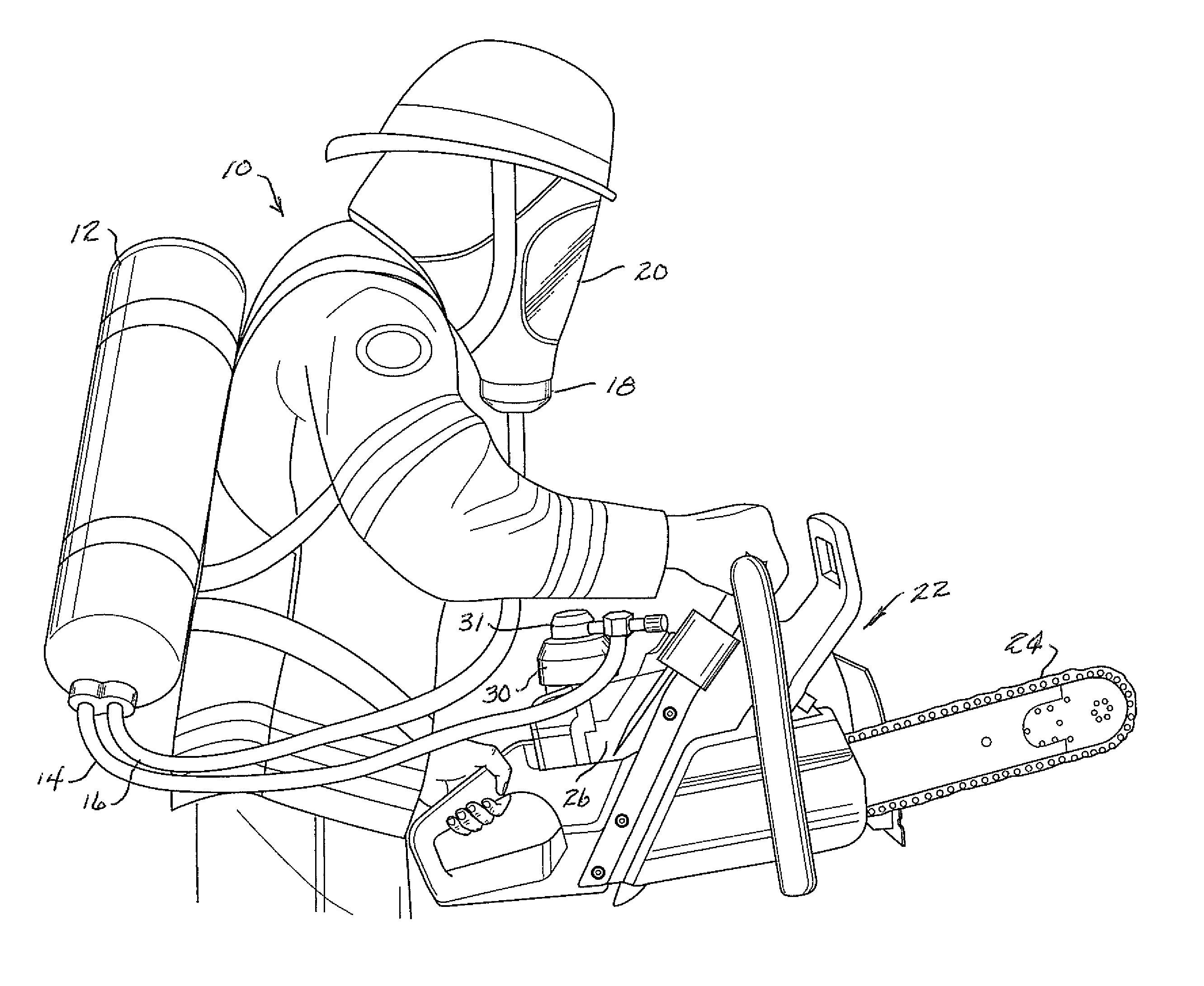
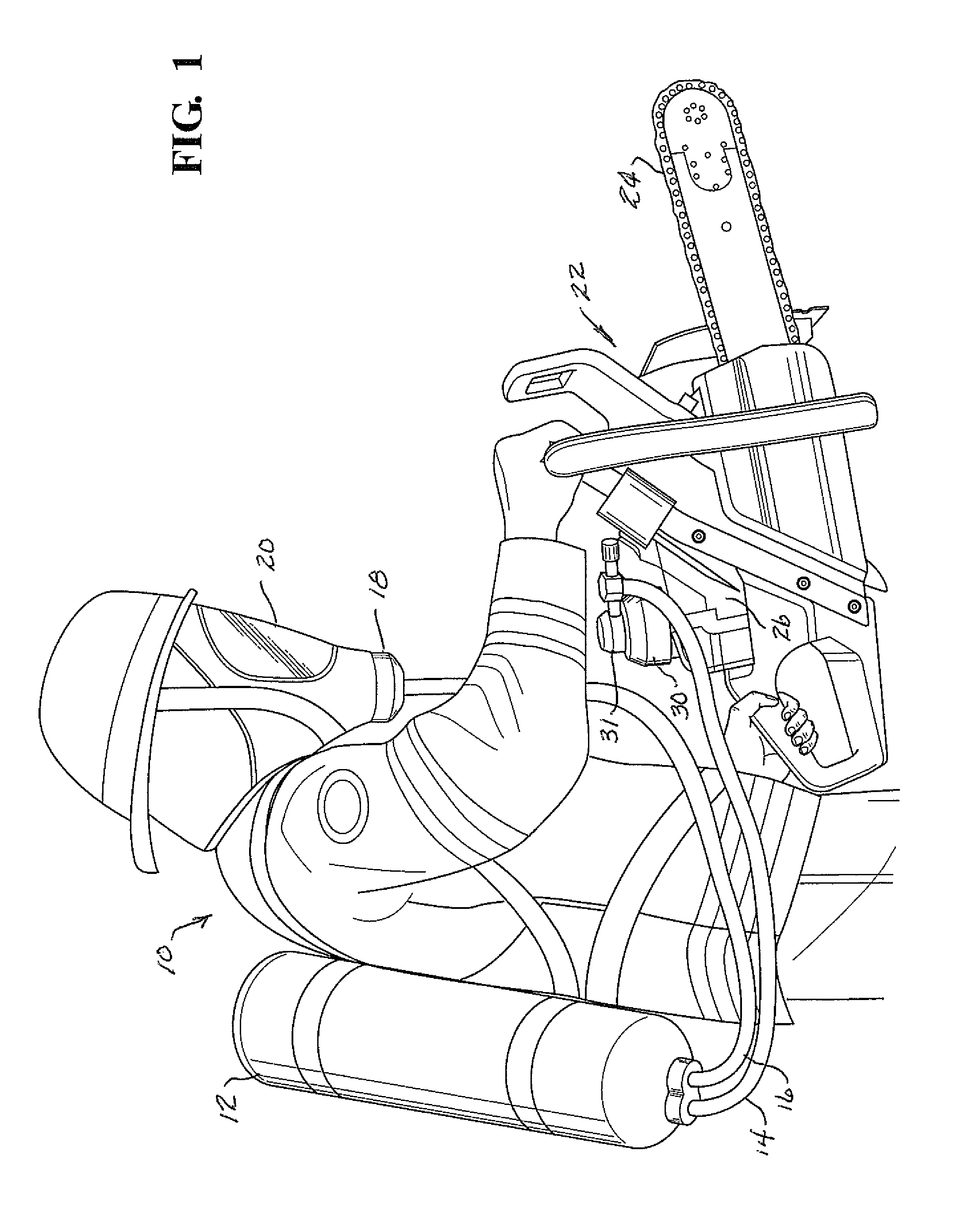
[0018]Referring now to the figures, FIG. 1 shows a firefighter 10 in full dress carrying on his back a compressed air tank 12 having two parallel outlet / supply conduits 14, 16 of which the conduit 16 is connected to supply air to a demand-type regulator 18 associated with a personal breathing apparatus including a mask 20 worn by the firefighter 10. The mask 20 is of the type having a clear Plexiglas viewing pane and of sufficient size to cover the entire face of the firefighter. Although not shown, the mark may incorporate a microphone and earpiece or speaker so that the firefighter can communicate with other firefighters or a director at the scene of operations.

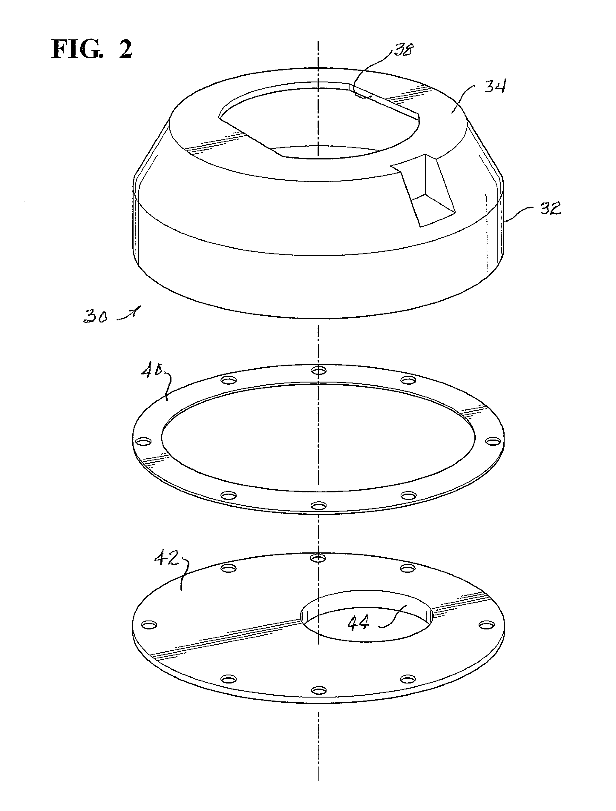
[0019]As further shown in FIG. 1, the firefighter is carrying an appliance in the form of a chainsaw 22 having a cutter bar 24 driven by an internal combustion engine 26. The engine 26 has a cylindrical air intake 28, best shown in FIG. 6. An adapter 30, more fully described with reference to FIGS. 2 and 3, is mounted on th...


PUM


Abstract

A system for simultaneously supplying compressed air to the personal breathing apparatus of a firefighter and to an internal combustion engine appliance, such as a chainsaw. The supply of air intake of the chainsaw is provided by means of an adapter which is configured to attach to both the air intake of the chainsaw and to a demand valve-type regulator.

Description

FIELD OF THE INVENTION[0001]The invention relates to firefighter's appliances and, in a specific embodiment thereof, to a system for simultaneously supplying air to a firefighter's personal breathing apparatus and to an internal combustion driven appliance, such as a chainsaw.BACKGROUND OF THE INVENTION[0002]Firefighters are often confronted with the need to enter an area which, because of an existing or previous fire, is breathable air-deprived to the point where neither a firefighter nor an internal combustion driven appliance, such as a chainsaw or cutter, can function to full effect. While it is known to supply the firefighter with a personal breathing apparatus fed by a tank of compressed air, a tool such as a chain saw or circular saw, when needed, is left to run at reduced horsepower, if at all, on whatever air or oxygen is left in the area that the firefighter has entered.[0003]Appliances such as chainsaws and cutters are often needed to clear debris or provide either or bot...

Claims


Application Information

Patent Timeline
IPC IPC(8): A62B7/12B23D57/02A62B9/02A62B9/04A62B7/02A62C8/00
CPCA62B7/12A62B7/02B23D57/023A62B9/022A62B9/04A62C8/00A62B3/005
Inventor SOLLIDAY, PAUL A.
Owner SOLLIDAY PAUL A
Learn More